Mikrotik: update WiFi PSK with randomly generated password and send it in telegram

Recently I upgraded my home WiFi with mikrotik cAP ac, the main reason to do it was an intention to configure guest WiFi with transparent traffic routing via TOR. Since I have intention to share guest password freely, I needed a way to change it from time to time. Firstly I wanted to make a telegram bot which would change wifi password via api call, but later I learned that it may be done with ugly scripting language which device supports.
More than that it has HTTP client, so I can change password by schedule and send it in telegram.

Here is the pre-requisites:
First, you should register the new bot with help of BotFather and get bot token, it looks like 110201543:AAHdqTcvCH1vGWJxfSeofSAs0K5PALDsaw
Second, you need to get your chat id with bot. I got it by sending a message to newly registered bot and fetching an update with curl:

$ curl 'https://api.telegram.org/bot110201543:AAHdqTcvCH1vGWJxfSeofSAs0K5PALDsaw/getUpdates'|jq '.result[].message.chat.id'

(chat id looks like 76615696).

The next thing to do is to create some sort of function to send message to telegram, it may be created with CLI or in WebFig -> System -> Scripts. Name tg_send, policy: read, write, policy, test

:local BotToken "110201543:AAHdqTcvCH1vGWJxfSeofSAs0K5PALDsaw";
:local ChatID "76615696";
:local ParseMode "html";
:local DisableWebPagePreview True;
:local SendText $MessageText;
 
:local tgUrl "https://api.telegram.org/bot$BotToken/sendMessage?chat_id=$ChatID&text=$SendText&parse_mode=$ParseMode&disable_web_page_preview=$DisableWebPagePreview";
 
/tool fetch http-method=get url=$tgUrl keep-result=no;

It’s important to replace BotToken and ChatID with your own token and id.

Previous script allows to make notification when password changed, the next one do the trick. Name: change_guest_pw, policy: read, write, policy, test, password.

:local ProfileName guest
:local DeviceName [/system identity get name];
:local PW ([:pick ([/certificate scep-server otp generate minutes-valid=0 as-value]->"password") 0 10])
 
 
:interface wireless security-profiles set $ProfileName wpa2-pre-shared-key="$PW";
:local MessageText "\F0\9F\94\91 <b>$DeviceName:</b> new guest pw: <code>$PW</code>";
:local SendTelegramMessage [:parse [/system script get tg_send source]]; 
$SendTelegramMessage MessageText=$MessageText;

Here is important to replace ProfileName with your own security profile which is ‘guest‘ in my case.
After that change_guest_pw can be scheduled to be executed regularly.

mikrotik-PSK-change

PS
One of the first thing which I noticed when I got the new access point was useless hardware button which just switched off all LEDs. It’s possible to use it as a trigger for script execution.
Cli commands:

/system routerboard mode-button
set enabled=yes on-event=change_guest_pw

make it change WiFI password as well or it may be configured in WebFig -> System -> RouterBoard -> Mode Button

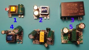
Test of 5 AC-DC PSUs cheaper than $1.5

I need  220AC to 5V PSU for exhaust fan controller, the trickiest part – it should be as small as possible. The main load is LEDs, same time supplied voltage should be clean enough for analog to digital conversions doing by attiny85. So I bought and test 6 different PSU. Because of seller mistake one of them turned up to be 220 to 12V PSU, so only 5 of them were tested.

TL;DR
All of them produces awful output exception of #1 and #3 (hilink)
The winner is #1, it’s one of the smallest (12X25X18 mm), one of the cheapest ($0.77), rated at 5V 700mA power supply.
No one of them (with exception of hi-link) doesn’t look safe enought to be treated as galvanic isolated PSU.
Here is a table for quick comparison, but out of the box (without changing capacitors or adding filters), only #1 and #3 worth to buy:

Continue reading

Repairing of kitchenaid phase control board

It’s a story how I spent thee days troubleshooting 9 elements circuit when 7 of them are passive. I didn’t found what’s wrong, but fixed it.

Foreword:
I have  control board marked as W10354309, it’s European 220V model of phase regulator.
I wonder which logic behind kitchenaid’s parts marking, I found several part numbers for 220V version: 3184417, 4163707, 4163712, 9701269, 9706596, W10217542, W10538289, W10911442, W11174552, WPW10538289
(110V version have same idea and same schematic, just different values and ratings for some elements)
I don’t know why they do that. Probably because they use the same part on different models and/or under different brands.
So, I have 5ksm125 mixer and W10354309 phase control.

Service manual says, that at the first speed planetary shaft should have near 60RPM, but in my case it had near 120RPM and I was unable to decrease it by tuning control plate.

Here I should make a digression, these mixers have ability to maintain constant RPM under different load.  I was surprised when I learn how do they do that. One of the main component comes right from the steam engine era, it’s centrifugal governor which is placed on the shaft of the motor, here it is:
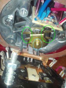
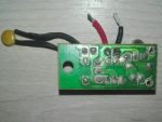
Yellow thing is the governor itself, black cylinders highlighted with green – weights, central pin stroked with blue is a pin which provides feedback to control plate. It works simple, the more RPM motor have the more pin extends.

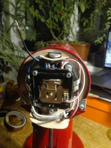
Next component is so called control plate, in fact it has simple main switch and a T shaped contact. The main switch  just break circuit when you move switch lever to off. T-contact plate just shorts contacts on a plate in 3 different configuration. The white tab on a picture above is a dielectric tab on T-contact, governor’s central pin pushes this tab and changes which contacts are closed on control plate. Here is control plate from the other side:
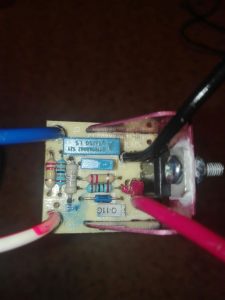
And the last component is a phase control board, it’s basically dimmer if you google for ‘dimmer circuit’ you will find the same scheme as used in phase control board with one exception, usually dimmers have variable resistor for smooth regulation, phase control board has resistors network in which resistors shorts by control board in 3 different configuration. You can see it  behind top edge of contral board on the picture above and on closeup photo on picture below:
So, how its work together? Here is schematic from repair manual with comments and nominals added by me:
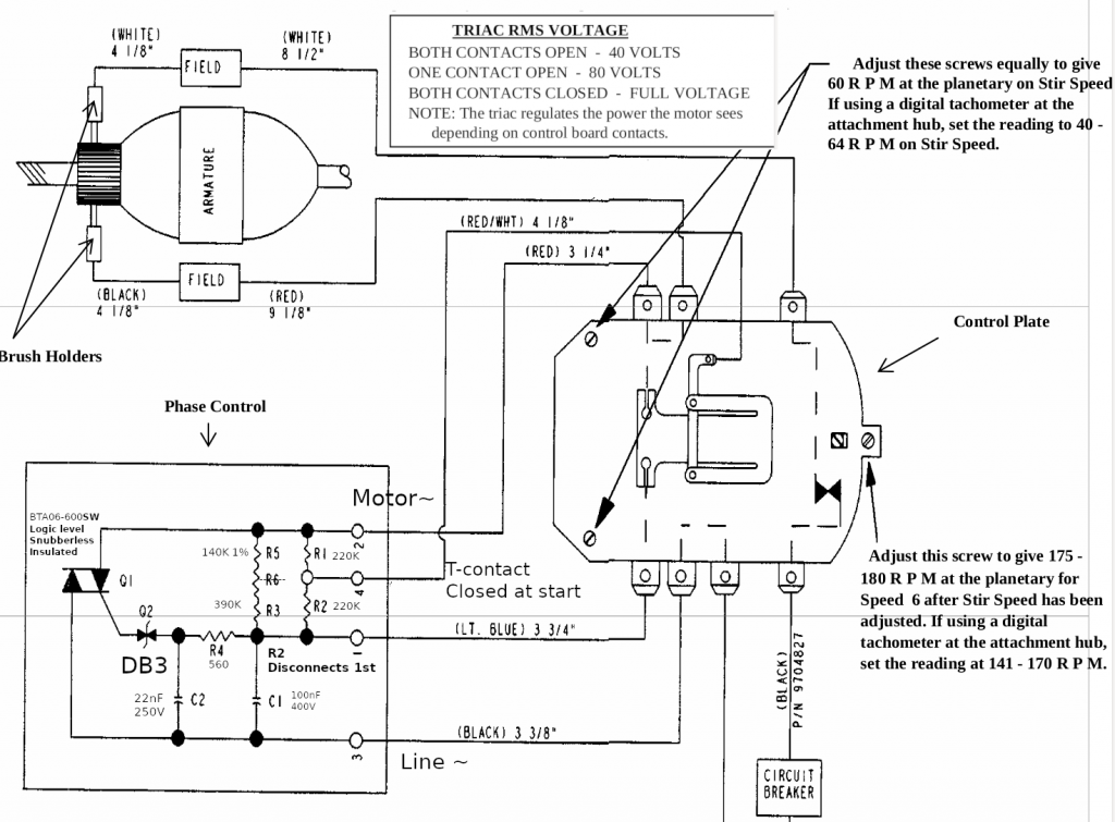
As I sad before control plate can be in 3 different states:
The first: the motor has too low RPM or doesn’t turn at all. T-contact fully closed, it shorts resistor network (R1, R2, R3, R5) completely and feeds motor with almost full sine wave (DIAC Q2 opens at around of 30V, so the start of the wave is chopped a little bit)
The third: the motor has too much RPM. T-contact fully opened, resistors network has maximum resistance,  phase control board feeds motor with minimum amount of energy (manual says that it should provide 40V RMS, I don’t understand why it’s true for both 110V and 220V version, but looks like it is).
The second: this state is somewhere in between too low RPM and too much RPM, control board shorts R1, equivalent resistance is ((R5+R3)* R2)/(R5+R3+R2), manual says that it should provide 80V RMS.

The more RPM motor have, the more central pin of centrifugal governor extents, the more it shift T-contact. When T-contact shifting, it opens circuit with bottom contact first and with upper contact next (check schematic above). When you select mixer’s speed you change distance between control plate and governor, the more distance it has the faster motor should spins to get equilibrium between the first and the third states.

Finally I can tell about my issue.
Usually when phase control is broken mixer doesn’t cho-cho at all or doing it on max speed, my story was slightly different, it had near 120 constant RPM on the first 3 speeds, next speed or two  increased RPM to the maximum, and other speeds did nothing.

When I saw schematic, I was pretty sure that I just need to replace DIAC. In circuits like this, if something works wrong in 99 cases of 100 it caused by broken semiconductor. When TRIAC failed it usually stays open or shorted (motor shouldn’t run at all or run at full speed).

I changed DIAC but  nothing changed, motor had RPM above nominal, but not the maximum. RPM was enough to extent governor’s central pin to the maximum and open both contacts on control plate.

The next suspect was TRIAC, here is only two semiconductors, if one of them is OK, the other one is broken, right? Wrong. I tried two different TRIACs without success. BTA12-600SW (it has the same characteristics like original one. Logic level gate, gate’s current 10mA , snuberless, but rated for 12A instead of 6A) and BTA06-600CW ( it isn’t logic level and had gate current around 35mA, it produced visible sparks during re-commutations on control plate, so don’t use it).

What should be suspected next? Capacitors? Both had less than 5% difference of capacitance from their nominals. I tried other capacitors, RPM of motor changed, but not significantly (in theory failed capacitors may have noticeable different capacity under high voltage, but I tested them with low voltage LCR meter).

After that I started to go crazy, I even de-solder every resistor, but they had correct values.
I spent near 3 days trying to find what’s wrong.
I had a lot of theories: failed resistor which heats when voltage applied and changes its resistance, semi-broken wires, semi-broken motor etc.
I even found a topic in which people had the same issue, but no one find the solution: https://www.electronicspoint.com/forums/threads/kitchenaid-mixer-phase-control-board-problem.241021/page-2

Soon after I started my experiments, I found that everything works as expected when I put R4 with increased value, but I wanted to find why circuit which had right elements didn’t work as it should.
At the end of the third day I gave up. I tried to replace every resistor, every capacitor in circuit and it didn’t helped, I tried to solder wires in parallel with existent,
In the end I decided to put 3.6KOhm R4 instead of original 560Ohm.

Here is my observations:

  • Manuals says that you can check phase control by putting sheet of non conductive material (like papper) between T-contact and contact which it touches, if it’s OK it should provide around 40V, but I got 50V. When I lovered voltage to 40V I got response from control plate regulation.
  • Motor starts spinning at around 9V DC.
  • Coils of stator has resistance of 7.8 Ohm each, rotor has resistance near 4 Ohm between nearest contacts, resistance of motor (between red and white wire) near 40 Ohm.
  • Circuit is sensible to element’s values, even when I tried to put capacitors with the same value I got slightly different RPM. My circuit has 1% R5, old scheme from manual has 3 resistors in series, usually this approach used when resistors have breakdown voltage less than voltage drop on them or when you want to use few cheap 5% 10% resistors instead of precise one.
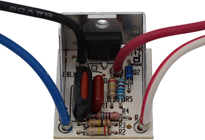
  • Probably phase control boards with  different part numbers more stable. I found photos of others boards and saw that resistors have values different from values that observed. Here is an example from amazon:
Simple temperature controlled fan regulator

Some time ago I pulled out temperature fan controller from one of old ATX PSU.
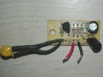
With 12.2V input it provides 4.5V at 25°C and raises output voltage till 11.8V at ~70°C. After changing Q2 to higher voltage transistor and tuning of R4-R5 this divider this controller should be suitable for 12V fans with 24/36/48V input.
Here is result of my reverse engineered schematic:

One and a half port charger on TP5100 module

WARNING: Lithium batteries can be extremely dangerous when handled unproperly and lead to fire hazard. Information provided as is, you can use it on your own risk.

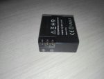
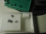
Before last holidays I bought cheap Chinese action camera, which came without separate charging station. Camera’s battery could be charged only in camera, charging batteries via which have few cons:

  1. You can damage camera port
  2. If you have more than one battery, you can charge only one at time
  3. You need to watch charging process and change batteries
  4. The last cons depends on camera, but usually compact devices use charger IC with linear regulation and they have low efficiency. If you don’t have access to electrical line and you bound to use power banks, efficiency could be critical.

It’s turned out that a lot of cheap cameras use battery in the same form-factor, thus I decided to share my charger.
I think the most popular solution for single-cell DIY Li-Ion chargers is TP4056 module. It’s almost plug and play solution, usually it have USB port and protection circuit, but it uses linear regulation, so it have low efficiency. Since efficiency is critical for me, I choose TP5100 module, unfortunately it comes without USB port, but it based on buck topology and should be much more efficient than TP4056.
Unfortunately these modules come without USB port (at least I didn’t found TP5100 with USB port).

Thus that project was separated in two main tasks: design carrier board with USB port and design case for charger.

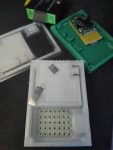
Carrier board is extremely simple, it contains only Micro-USB port and place for TP5100 module.

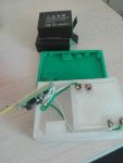
Case also has simple design, only curlpit which I had – contacts. I made them from nickel plated strips, which I bent once to make it bit thicker:

First I had design where contacts should be inserted from side, but it was nearly impossible because of  small gap between side wall and battery holder wall. I redesigned the case in a way when contacts inserted from bottom, un-fortunatelly I didn’t take into account that wires should be soldered from bottom, so supports under contacts should be re-designed or partially melted with solderer as I did it.
To make contacts stiff I glued them in. If they not feet freely into dedicated slots, use solder iron to melt them into slots.
Before gluing them into place, you should be sure that they are long enough and battery fits properly. I supported contacts with fingers during tests. If they have right size, battery should ‘click’ into slot. My batteries stayed in place even when charger with batteries was turned upside-down.

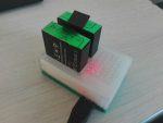
Upper case was printed in with ‘transparent’ plastic, so I can see status led soldered on charger module:

Here is start most interesting part. TP5100 can charge two cells connected to serial, but cells will not be balanced. With a camera I frequently have one partially depleted battery and one fully depleted battery, so I cant charge them in serial configuration without balancer.
Same time it’s not recommended to connect in parallel batteries which discharged un-equally, because current which will flow between batteries will be limited only by resistance of wires and internal resistance of batteries itself.
For myself I decided that it’s acceptable risk because of next reasons:

  1. Batteries like that is not high current, so they should have relatively high internal resistance which will limit current
  2. I especially use thin wires, which have their own noticeable resistance
  3. Contacts also have noticeable resistance
  4. When one battery charges another their potentials aligns. The less difference in voltage the less current flows
  5. I’m planning to connect batteries only when charger powered up, so up to 1A from charger will aligns their potential.

When I did the charger, I connected fully charged battery with battery which was just discharged by camera and measured the current, it was near 0.17A. Batteries like that should be ok at 1C current (0.9A in my case).
I will not agitate anyone to do the same, but I find it ok for myself.

Two more precautions, this charger can be connected only to chragers which are provide more than 1A current. Newer connect that charger to laptop or PC.
TP5100 usually come with maximum charging current set as 1A. If you put 1 battery, it’s a bit more than 1C (0.9A in my case), but I didn’t observed any noticeable warming of battery during charge cycle, so you can set charge current lower or use it with 1A on your own risk.

Here is stl files for  case
Board files: board

Upgrade XTLW3 with MKS Sgen_L & smoothieware

I own XTLW3 3D printer which come with MKS Gen_L  8 bit board and MKS MINI12864 display, out of curiosity I decided to try 32 bit board, one of the cheapest option is MKS Sgen_L  board. Earlier I used marlin firmware on gen_l board, but sgen_l come with smoothieware, so I decided to give it a try.

Looks like the most important advantage of smoothie firmware in comparison with marlin is ability to define your machine settings without re-compiling firmware. You can configure axis resolution, endstops, etc via regular text config file on a sdcard. That approach helps to fix mistakes during configuration or make experiments easily without re-compiling and re-flashing firmware.
Few weeks ago I mounted 3Dtouch sensor (BLtouch’s chinese copy), but I delayed moment of connecting it, anticipating related problems with re-configuring and re-flashing Marlin. Thereby it  was perfect moment to try new firmware.

There MKS provides example config which partially fits my printer, I managed to make it work and here is notes which may be helpful to somebody:

End stops and physical boundaries should be defined, my printer have end stops placed at minimal position for X&Z axis and at maximal position for Y axis. All of them are Normally Opened and connects sense pin to ground when activated, so pull up should be enabled. In XTLW3 hotend nozzle is not above print bed, because end stops misaligned. For me it’s even better, because I made printer dumps small amount of plastic during init procedure paste the table, in that way it doesn’t lie on the bed.
Here is my part of config for end stops and boundaries:

# Limit switch setting
endstops_enable true
soft_endstop.enable
soft_endstop.halt           true   # Whether to issue a HALT state when hitting a soft endstop

## X-axis
alpha_min_endstop 1.29^!
alpha_homing_direction home_to_min
alpha_min           -2
alpha_max           220
soft_endstop.x_min  1
soft_endstop.x_max  220

## Y-axis
beta_max_endstop 1.26^!
beta_homing_direction home_to_max #
beta_min -3
beta_max 224
soft_endstop.y_min          1
soft_endstop.y_max          220

## Z-axis
gamma_min_endstop 1.25^!
gamma_homing_direction home_to_min #
gamma_min -3 #
gamma_max 280 #
soft_endstop.z_min          1            # Minimum Z position
soft_endstop.z_max          285          # Maximum Z position

BTW, you should not exceed 132 characters per line. Also smoothieware uses different naming for axes in comparison with Marlin. For Cartesian based printer aplha means X, beta means Y and gamma means Z.
End stop value is just a pin name (mine placed right on the board), ‘^’ suffix enables pull-up and ‘!’ suffix inverts signal.
End stops configuration can be checked by issuing ‘M119’ g-code in printer’s terminal. You need to achieve all endstops to be reported as ‘0’ when they are not triggered and  ‘1’ when they are all triggered, ie:

X_min:1 Y_max:1 Z_min:0 pins- (X)P1.29:1 (Y)P1.26:1 (Z)P1.25:0 Probe: 0

Here you can see that X and Y end stops was triggered in opposition with  Z which was open.
You need to specify your homing direction in direction where your end stops are placed. I specified to home Y axis to max, because I had end stop at max position in contrast to other axis.
alpha/beta/gamma_min/max – options used to specify physical dimensions of axes. My printer has square rectangular table specified by two points (1,1; 220,220), but head can move besides that coordinates.
When head homed by XY it home outside of table space:

So when I set negative values or values larger than actual table, I just shifted origin, to make it placed on a corner of print table.
Soft limits just set boundaries for G<X> movement codes, they prevents movements which may damage  printer.

I don’t want to make a saga from that post, so I will  continue in the next posts.

Lenovo battery hack and whitelist at the same time

Recently I’ve got x230 laptop and have a plan to change buggy Intel Centrino 6205 adapter to something like Atheros, also I decided that it’s worth to have ability to use x220 like batteries, just in case.
To achieve that, I needed to flash patched firmware for EC controller (thinkpad-ec project) and modified bios (1vyrain project), but it was confusing, what should go first? Firstly I didn’t realised that thinkpad-ec flashes only EC firmware, it looked like EC mod will update bios to newer version than supported by 1vyrain, same time 1vyrain would update bios to version newer than supported by thinpkad-ec.
Finally, here is how to have EC mod together with patched BIOS on x230 laptop:
1. BIOS should be old enough to be compatible with  1vyrain and thinpkad-ec, at 2020-03-22 it should be not newer than 2.60 (1vyrain has requirements of more older bios than thinkpad-ec, requirements for 1vyrain patch can be found here)  otherwise it should be downgraded as described here.
2. Make bootable device with thinkpad-ec image, in BIOS set boot mode to ‘Legacy’ and update EC firmware.
3. Make bootable device with 1vyrain image, in BIOS set boot mode “UEFI only”, disable “Secure boot” and update BIOS.

In my case I ended with BIOS version 2.77 EC version 1.14.

STM32Cube FW_F1 V1.8.0 package breaks HAL time source init

As a hobby I’m working on a growbox controller which based on stm32 MCU. Yesterday I got STM32Cube MCU package update, as many times before I just upgraded package and project to latest version, as result firmware started to stuck in assert_failed().

It happens during call of SystemClock_Config() (defined in main.c) which in turn calls  HAL_RCC_ClockConfig(), which in turn calls HAL_InitTick(uwTickPrio) at Drivers/STM32F1xx_HAL_Driver/Src/stm32f1xx_hal_rcc.c:947:

...
  /* Update the SystemCoreClock global variable */
  SystemCoreClock = HAL_RCC_GetSysClockFreq() &gt;&gt; AHBPrescTable[(RCC-&gt;CFGR &amp; RCC_CFGR_HPRE) &gt;&gt; RCC_CFGR_HPRE_Pos];
 
  /* Configure the source of time base considering new system clocks settings*/
  HAL_InitTick(uwTickPrio);
 
  return HAL_OK;
}

When it happens uwTickPrio still have invalid interrupt priority, which is defined in Drivers/STM32F1xx_HAL_Driver/Src/stm32f1xx_hal.c:80:

...
/** @defgroup HAL_Private_Variables HAL Private Variables
  * @{
  */
__IO uint32_t uwTick;
uint32_t uwTickPrio   = (1UL &lt;&lt; __NVIC_PRIO_BITS); /* Invalid PRIO */
HAL_TickFreqTypeDef uwTickFreq = HAL_TICK_FREQ_DEFAULT;  /* 1KHz */
...

Only one place where uwTickPrio can be updated is ./Drivers/STM32F1xx_HAL_Driver/Src/stm32f1xx_hal.c:234:

__weak HAL_StatusTypeDef HAL_InitTick(uint32_t TickPriority)
{
  /* Configure the SysTick to have interrupt in 1ms time basis*/
  if (HAL_SYSTICK_Config(SystemCoreClock / (1000U / uwTickFreq)) &gt; 0U)
  {
    return HAL_ERROR;
  }
 
  /* Configure the SysTick IRQ priority */
  if (TickPriority &lt; (1UL &lt;&lt; __NVIC_PRIO_BITS))
  {
    HAL_NVIC_SetPriority(SysTick_IRQn, TickPriority, 0U);
    uwTickPrio = TickPriority;
  }
  else
  {
    return HAL_ERROR;
  }
 
  /* Return function status */
  return HAL_OK;
}

But this function is redefined in ./Core/Src/stm32f1xx_hal_timebase_tim.c:42:

HAL_StatusTypeDef HAL_InitTick(uint32_t TickPriority)
{
  RCC_ClkInitTypeDef    clkconfig;
  uint32_t              uwTimclock = 0;
  uint32_t              uwPrescalerValue = 0;
  uint32_t              pFLatency;
 
  /*Configure the TIM4 IRQ priority */
  HAL_NVIC_SetPriority(TIM4_IRQn, TickPriority ,0);
 
...

And doesn’t contain proper uwTickPrio initialization, as result it’s called with invalid TickPriority  and fails into assert_failed() during HAL_NVIC_SetPriority(TIM4_IRQn, TickPriority ,0) call.

How to just send logs from files to graylog2

That solution allows to read logs from file and just send them to remote syslog/graylog server. Logs will not influent on current syslog settings, you won’t need to filter them out of any syslog facility (like local7), all you need – the rsyslog (I’ve used v8).

My task was to send logs which wrote by java application (if I’m right log4j was used), they were rotated by logrotate with truncation, so few specific options were added.
I replaced %APP-NAME% in rsyslog’s template(RSYSLOG_SyslogProtocol23Format) to be able differentiate from which files log messages were read.

As for me, it’s better to write logs in format which allow them to be parsed easily or send them right to remote location , but if you need to do it quickly without modification of application it’s appropriate solution. Just copy config below in file like  /etc/rsyslog.d/99-graylog.conf and modify TARGET.ADDRESS, TARGET.PORT, app_ tag and File setting according to your environment.

module(load="imfile")

template(
name="SyslogProtocol23Format_modified" type="string"
string="<%PRI%>1 %TIMESTAMP:::date-rfc3339% %HOSTNAME% %syslogtag%%$.suffix% %PROCID% %MSGID% %STRUCTURED-DATA% %msg%\n"
)

ruleset(name="sendToLogserver") {
action(type="omfwd" Target="TARGET.ADDRESS" Port="TARGET.PORT" Template="SyslogProtocol23Format_modified")
}

ruleset(name="app_logs") {
set $.suffix=re_extract($!metadata!filename, "(.*)/([^/]*)", 0, 2, "unknown.log");
call sendToLogserver
stop
}

input(
type="imfile"
File="/var/log/app_logs/*.log"
Tag="app_"
Ruleset="app_logs"
freshStartTail="on"
addMetadata="on"
)

In my case application wrote multi-line log messages, so startmsg.regex was used. Also logs were rotated by logrotate with truncate method, additional option reopenOnTruncate was used. So my input section looked like:

input(
type="imfile"
File="/var/log/app_logs/*.log"
Tag="app_"
Ruleset="app_logs"
freshStartTail="on"
addMetadata="on"
startmsg.regex="^[0-9]{4}-[0-9]{2}-[0-9]{2} "
reopenOnTruncate="on"
)