Simple OpenVPN profile generator

Few month ago i learned that OpenVPN support profiles. Before that i generate config for every client, create keys and certs with easy-rsa, tar it’s all together and put on client. Now i can create profile that will contain all necessary keys, certs and config in one file, so i write simple script that generate .ovpn profile for new client.
Generated .ovpn profile can be imported from sd card in Android, via iTunes or email in iOS, or just type `openvpn your_new_profile.ovpn` at PC.
Prerequisites: configured easy-rsa (`pkitool clientname` must produce cert and key for client).
You must customize config part for your server, it is possible to fetch data from server config file, but i’m too lazy to modify script for it.
There is it:

#!/bin/bash
#Dir where easy-rsa is placed
EASY_RSA_DIR="/etc/ssl/easy-rsa"
KEYS_DIR="$EASY_RSA_DIR/keys"
# Dir where profiles will be placed
OVPN_PATH="/root/ovpn"
REMOTE="your.server port"
 
 
if [ -z "$1" ]
then 
        echo -n "Enter new client common name (CN): "
        read -e CN
else
        CN=$1
fi
 
 
if [ -z "$CN" ]
        then echo "You must provide a CN."
        exit
fi
 
cd $EASY_RSA_DIR
if [ -f $KEYS_DIR/$CN.crt ]
then 
        echo "Certificate with the CN $CN already exists!"
        echo " $KEYS_DIR/$CN.crt"
else
source ./vars > /dev/null
./pkitool $CN
fi
 
cat > $OVPN_PATH/${CN}.ovpn << END
client
dev tun
resolv-retry infinite
nobind
persist-key
persist-tun
verb 1
comp-lzo
proto tcp
remote $REMOTE
 
<ca>
`cat $KEYS_DIR/ca.crt`
</ca>
 
<cert>
`sed -n '/BEGIN/,$p' $KEYS_DIR/${CN}.crt`
</cert>
 
<key>
`cat $KEYS_DIR/${CN}.key`
</key>
END

KIS-3R33 calculator

Half year ago i wanted to get  in car  PSU to charge my smartphone or to power devices like camcoder. I wanted to build powerful  power supply, first i tried to build it on chip NCP3155, but has failed. I lurking around to find another chip and found complete module KIS-3R33 based on MP2307 chip. I found it very interesting and cheap, after i got few i started to find way how to change output voltage from 3.3V to 5V. I found many guides how to change Vout, by replacing internal components and all of them ignore the fact, that module have Adjust pin. I wanted to find way how to change Vout without replacing internal components.
KIS-33R3 very similar to  typical application:
screenshot14
Datasheet give ratio for calculation of Vout depend of R1 and R2:
Vout = 0.925* (R1 + R2) / R2
According to scheme of module that i found into the internet, Adjust pin connected to FB in series with resistor of 3.3kOhm:
Kis-3r33s_Diag.jpg

R1 = 25.5 kOhm (two 51kOhm resistors in parallel), so it is possible to vary R1 in range 25.5 kOhm – 2.9 kOhm and R2 in range 10 kOhm – 2.48 kOhm it give output range 1.19V – 10.43V. If you need voltage more than 5V, you need to remove zener diode first (D2 on scheme), because this diode limit Vout to 5.1V. Also voltage range of output capacitor (C2 on scheme) is not know, so it is good idea to replace it with capacitor that can handle your output voltage.
I wrote simple calculator for KIS-3R33 that compute resistor that you must connect between Adj pin and GND or Vout to get desired voltage. Don’t forget, that result will correct only for KIS-3R33 that have 3.3V output (i seen version that have 2.7V output, so be careful).

Vout = V

NaN

Libvirt + vnc + sasl

Error: connection to hypervisor host got refused or disconnected!Yesterday i wanted to configure libvirt with kvm virtualization, while i read comments in config file, i observed, that qemu can share credentials  with  libvirt via sasl. Also i found few how-to, that said ‘just copy /etc/sasl2/libvirt.conf to /etc/sasl2/qemu.conf’.
I done that, but when i tried to open console of VM i got “Error: connection to hypervisor host got refused or disconnected!”.
May be you think, that you can find something interesting in log? Nope. May be you think that you can run virt-manager in debug mode and will see something useful? Nope. The reason, why this happened is because, libvirt  run as root, but they start VM’s as libvirt-qemu user. And sasl2 database has owner root:root and 640 permissions. I changed owner of /etc/libvirt/passwd.db to libvirt-qemu:root and problem is gone.

STM32 performance test or how fast you can serve input signal

Finally, i decided to try stm32, before i wrote firmwares only for AVR mega family (from now, when i say AVR MCU, i mean AVR mega family MCU), and was scared by tonns of code that you need for simply led blinking on STM32 MCU.
Now i can say, that programming of STM32 not so hard as it looks first time. After i understand logical structure of MCU core and how it work, it become easy.
OK, it was prelude.

Every time when i see comparison between AVR and STM32/STM8 MCU’s i faced with next arguments:
STM MCU’s have lower price, when they have more RAM, FLASH, GPIO pins and work frequency. Looks sweet. Today i want to tell the story about work frequency.

More than the operating frequency of the MCU, the faster it can handle events. STM32 MCU’s have maximum work frequency more than 20MHz (72MHz for STM32F103 that i have), when AVR MCU’s have only 20MHz. Is 72MHz a lot of or not? Two week ago i wanted to know, is it enough ~200MHz of STM32F4 to handle 10MSPS ADC on not? Two weeks ago i think ‘may be’. Now i think ‘not enought’.

Last Friday evening i blow the dust from oscilloscope and made little research.
My basic code poll pin, by software, configured for input and set same signal on output pin, the code is there:

while(1) {
         if( GPIOB->IDR & GPIO_IDR_IDR10 ) {
                        GPIOB->BSRR = GPIO_BSRR_BS8;
         } else {
                        GPIOB->BSRR = GPIO_BSRR_BR8;
         }
}

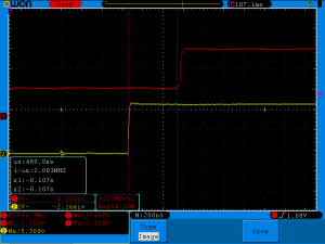
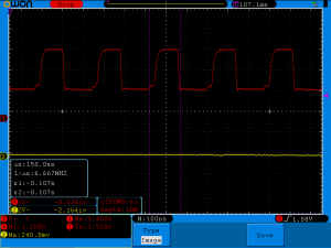
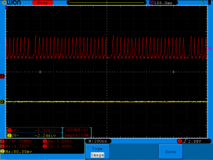
How many time MCU need to set same level on GPIO pin as on input pin?  May be 140nS (near 10 clocks on 72MHz) will enought?
stm32_delay_O0

Nope. 480ns. It near 34 cycles. The period of 480ns has frequency of 2MHz, may be i forgot to change speed of gpio port?

stm32_debug_toggle_pin_50MHz

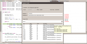
Nope. May be i forgot to switch on external quartz or forgot to configure PLL?

stm32_debug_pll

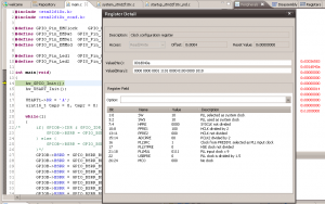
Nope. Hmm, may be optimization can help? Let’s try to switch on -O3:

stm32_delay_O3

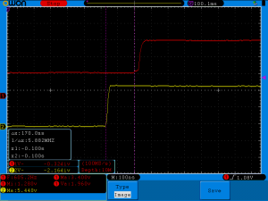
Much better, 170 ns. MCU need near 12 cycles, to detect signal and change state of one GPIO speed. Do not forget, MCU just pooling one pin and change state of another, it do not do valuable work.Okay, but what the maximum speed you can get, if you will just change the state of GPIO pin?
Is it possible to hit theoretical maximum of 50MHz (max clock speed of GPIO ports on STM32F103):

stm32_toggle_pin

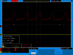
Just 6MHz. Let me switch on optimization for you:
stm32_toggle_pin_serial_0
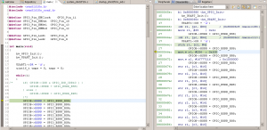
Looks like there only 36MHz, let’s look on the code:

stm32_debug_toggle_pin_O3
I can’t see why they can’t reach 50MHz. If you look on disassembler view, you can see, that MCU just store different values on constant address.
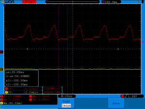
In fairness i must to say, if you set cursors on oscilloscope in different manner, you can achieve 50MHz:

stm32_toggle_pin_serial_1
It is hard to say what way of measurement is wrong, i think the second, because first time it is easy to see time of 2 periods. Without a doubt, the second way STM advertising department would have liked more.
BONUS:
A picture where is while cycle occurs:
stm32_toggle_pin_serial_burst

Pulseview compilation

Half year ago i wanted to make device that can be used to clone ski pass. I thought that ski passes use RFID 125kHz. First i bought itead module RDM6300 but it turned out that it can only read tags, so i bought  EM4095 chip. At this time i also noticed, that most ski passes use MIFARE tags that operated at 13MHz.
Anyway i want to complete this project and build device that can read and write 125kHz tags (really there is to many different tags that operate on 125kHz and uses different protocols, so i want to start with EM4100 tags).That tags use manchester encoding to transfer data, also tags can use different bitrate. It is easy task to encode data into manchester, but it’s really pain in the ass if you want to decode them and does not know bitrate.
I have clone of saleae logic analizer so i decided to practice with decode manchester with libsigrokdecode. Sigrok have ‘official’ gui for libsigrok and libsigrokdecode called Pulseview.
I found that debian wheezy have old libsigrok and do not have pulseview at all, after that i decided to build sigrok and pulseview from scratch. It is really not easy quest, because additionally to libsigrok, libsigrokdecode you need to compile old libusb and libvisa.
Finally when i compiled all that stuff, i faced with errors when i tried to compile pulseview with decoders support.

First, libsigrokdecode need Python >= 3.0, Python.h placed in python3.2/Python.h, so you need to change it into libsigrokdecode.h:

./include/libsigrokdecode/libsigrokdecode.h:#include <python3.2/Python.h> /* First, so we avoid a _POSIX_C_SOURCE warning. */

Second, if you will got that error:

[ 40%] Building CXX object CMakeFiles/pulseview.dir/pv/view/decodetrace.cpp.o
/var/tmp/sigrok/pulseview/pv/view/decodetrace.cpp: In member function ‘virtual void pv::view::DecodeTrace::paint_mid(QPainter&, int, int)’:
/var/tmp/sigrok/pulseview/pv/view/decodetrace.cpp:203:3: error: ‘hash_combine’ is not a member of ‘boost’
/var/tmp/sigrok/pulseview/pv/view/decodetrace.cpp:204:3: error: ‘hash_combine’ is not a member of ‘boost’
/var/tmp/sigrok/pulseview/pv/view/decodetrace.cpp:205:3: error: ‘hash_combine’ is not a member of ‘boost’
make[2]: *** [CMakeFiles/pulseview.dir/pv/view/decodetrace.cpp.o] Error 1

Then you need to add “#include <boost/functional/hash.hpp>” into /var/tmp/sigrok/pulseview/pv/view/decodetrace.cpp

Third,  if you got that:

CMakeFiles/pulseview.dir/pv/data/decoderstack.cpp.o: In function `pv::data::DecoderStack::decode_proc(boost::shared_ptr<pv::data::Logic>)':
/var/tmp/sigrok/pulseview/pv/data/decoderstack.cpp:267: undefined reference to `srd_session_new'
/var/tmp/sigrok/pulseview/pv/data/decoderstack.cpp:283: undefined reference to `srd_inst_stack'

You need to add -lsigrokdecode into CMakeFiles/pulseview.dir/link.txt

I spent too many time to compile that stuff, so i decided to place here archive with complete libsigrok, libsigrokdecode, libvisa, libusb, sigrok and pulseview. I compiled it with preffix /opt/sigrok, so if you want to use it, place that stuff into /opt and run like that:

LD_LIBRARY_PATH=/opt/sigrok/lib /opt/sigrok/bin/pulseview

Enjoy: sigrok.tar
md5: 7bbb1d434959848c741230fe90a590c5 /tmp/sigrok.tar.gz
PS
Also you must install  libboost-thread.

Arduino keyManager

Few months ago i started to developing iron for waxing my snowboard. Last season i bought regular iron and used it, but it can set temperature only in wide range, did not have overheat protection and can melt the base of the board. In university i learned of 8bit avr mcu, but all firmwares that we wrote, we wrote on ASM. Now it is my hobby and i decided to try C/C++ programming, early at school i wrote on C, but forget to many about C language, so now, after many years without practice, i decided to try arduino.
When i wrote arduino sketches i did not found library to manage keys. I wanted event based library that can produce events when key pressed, when key long pressed and when key released, also it must have program debounce.
Early to manage keys i just wrote tonnes of code right in sketches, but when sketches grow up, they started to looks like a crap, so i develop my own library.
They far away from to be excellent ( i am not very familiar with C, not to mention C + +), but they work.
Now code of the library have mixed russian and english comments ( hope i will change it in future ).
I tried to write library fast as possible and using minimal resources, because of that (and because i do not know C++ well) there to many hard coded defines for delay values in keyManager.h (debounce time, time to long press detection and time to regenerate long press event). I feel it is possible to make library better with C++ templates, but i did not found time to learn it well.
Last words, before i show example, library designed to be used with pull up keys, ie when key pressed, digitalRead() must return LOW.
I turned arduino blink example to work with key manager. There are two keys, one switched off the led, another on switch it on.

// Include library header
 #include <keyManager.h>
 
#define led 13
#define off_pin 10
#define on_pin 11
 
// Create keyManager objects, when you create key object, they
// initialize key pin as input 
keyManager on_key( on_pin, true );
keyManager off_key( off_pin, true );
 
void setup() {
  // initialize the digital pin as an output.
  pinMode(led, OUTPUT);
}
 
// Led state
uint8_t led_state = 0;
 
void loop() {
// This is main part, process() function must run at least once in every 255 micro seconds
// process() function is heart of the library based on FSM, they process
// key state changes and generate events
  on_key.process();
  off_key.process();
 
// Light led if on key pressed
  if( on_key.isPressed() ) {
    digitalWrite(led, HIGH);
    led_state = HIGH;
  }
// Swich off if right key pressed
  if( off_key.isPressed() ) {
    digitalWrite(led, LOW);    
    led_state = LOW;
  }
 
// If any key pressed long, led will change the state
  if( on_key.isLongPressed() || off_key.isLongPressed()  ) {
    if( led_state == LOW ) {
      led_state = HIGH;
    } else {
      led_state = LOW;
    }
    digitalWrite(led, led_state);
  }
}

Second argument of:

keyManager on_key( on_pin, true );

Select how keys will be driven. When argument is ‘true’ keys will managed in ‘event mode’ it means, that isPressed() will return true only once until you did no release key and did not press it again. Same for isReleased().
isLongPressed() will return ‘true’ first time, when key will be pressed longer than defined in keyManager.h (by default 1.5 sec) and after every repeat delay if key will not released (by default 0.1 sec).
Event generated every time when key changed their state, there is function isEvent() to check that. isEvent() return true until event will not received by isPressed(), isLongPressed() or isReleased(). In another words that functions will clear event flag after picked up their event.
keyManager can work in another mode, when second argument is ‘false’, functions isPressed(), isLongPressed() and isReleased() will not clear event flag, they return true every time when key in their state. Event flag will generated as before, but can be cleared only with clearEvent() function.
Now library use 4 bytes of ram to manage single button. In future i want reduce ram that used by timers, add more examples and simplify delays configuration.

There is link to github: https://github.com/IvanBayan/arduino-keyManager

How to use angled brackets in WP-Syntax

I often use WP-Syntax plugin for syntax highlighting. When i used angled brackets or ‘&’ symbol or something like that i recieved next garbage:

$ echo fail 2&gt;&amp;1 &gt;/dev/null

It happened because wp-syntax tried to escape special symbols, but <pre> tag says wordpress to show symbols as it passed into that tag. Early, before publishing i switched from visual into text mode and changed all that garbage into what i want. But solution is to add  escaped option into <pre> tag, <pre lang=”bash” escaped=”true”>, now same block will look like i expected:

$ echo congrat 2>&1 >/dev/null

Enjoy!

Zram

Few months ago, i tried very cool feature called ‘zram’. It is linux kernel module that allow to create compressed block devices into memory, it can be used for creating compressed fs in ram  (/tmp for example) or for swap.
May be you think, that in context of swap, it is dumb to keeping  memory pages in memory when OS need that memory. =) But compress and store pages in memory is faster than write it onto disk, in most cases memory pages can be heavily compressed, that will help OS to free RAM, if you have SSD it will save life of your disk, also you can continue using swap on disk. If you want to keep you swap partition on-line, you must give higher priority for swap in zram, when zram will full, OS will started to using swap on disk.

I used that init.d script for debian, but i changed it to use not  a whole RAM for zram devices, but half of all memory (in worst case, when pages can not be compressed, zram will use only half of my memory). If you want to do same modification, just change echo $((mem_total / num_cpus )) to echo $((mem_total / num_cpus / 2)) in that script.
Without modifications this script will slice you memory by number of CPU core in your system, create swaps on that slices and attach it to your system with priority 100 (usualy swap partitions have priority -1).
I made simple test of compression ratio for zram:
Detached one of my swaps:

$ sudo swapoff /dev/zram3

Created core file of iceweasel process and wrote it into zram:

$ pgrep -lf icewea
3375 sh -c /usr/bin/iceweasel
3376 /usr/bin/iceweasel
$ gcore 3376
[Thread debugging using libthread_db enabled]
[New Thread 0x7f7c0b9fd700 (LWP 8455)]
...blablabla...
0x00007f7c62a57c13 in poll () from /lib/libc.so.6
Saved corefile core.3376
$ sudo dd if=./core.3376 of=/dev/zram3
dd: writing to `/dev/zram3': No space left on device
2027297+0 records in
2027296+0 records out
1037975552 bytes (1,0 GB) copied, 6,79003 s, 153 MB/s

Core file does not fit completely into zram device, but it is dose not mater, let’s look at compression ratio:

$ cd /sys/block
$ echo `cat ./zram3/orig_data_size`/`cat ./zram3/compr_data_size`|bc
2.68475926964795164955

So, in most cases zram has compress ratio more than 2.5.
Huh, i think it is pretty cool.

Zoneminder jitter

After several years of torture with easycap i realize that it is time to change capture device. I found that other usb capture device that supported by linux cost to high, also i can not use PCI or full height PCI-e devices because of mATX form factor of my server.  Suddenly i found ImpactVCB 1381, it is what i wanted to found, it is supported by linux, PCI-e and has half height bracket.
Before i did not try it card i did not think, that it is can be so much difference in image quality between two cards. Unfortunately i do not have sample with  easycap, but you can trust me, difference is enough to throw easycap.
As always there is a fly in the ointment, zoneminder or haupage driver has bug and captured image sometimes jittering, it is looks like that:
Zoneminder jitter

I preferred to think, that it is bug in zoneminder, because i did not seen same issue when i captured video with mencoder.
Will hope it will be fixed in future releases.

You IP

Since the idiots in the Russian government passed a law similar to ‘SOPA’ i started to modify routing scheme at my home. Many times i used internet.ya.ru to determine my current outgoing IP address, but i wanted to use more minimalistic tool for this purpose. So i created my own tool with blackjack and hookers, there it is: https://ivanbayan.com/uip.php i using different routes for TLS and http traffic, so it is also available there  https://ivanbayan.com/uip.php.
This script produce simple image with you outgoing ip:

You ip