 It’s a story how I spent thee days troubleshooting 9 elements circuit when 7 of them are passive. I didn’t found what’s wrong, but fixed it.
Foreword:
I have control board marked as W10354309, it’s European 220V model of phase regulator.
I wonder which logic behind kitchenaid’s parts marking, I found several part numbers for 220V version: 3184417, 4163707, 4163712, 9701269, 9706596, W10217542, W10538289, W10911442, W11174552, WPW10538289
(110V version have same idea and same schematic, just different values and ratings for some elements)
I don’t know why they do that. Probably because they use the same part on different models and/or under different brands.
So, I have 5ksm125 mixer and W10354309 phase control.
Service manual says, that at the first speed planetary shaft should have near 60RPM, but in my case it had near 120RPM and I was unable to decrease it by tuning control plate.
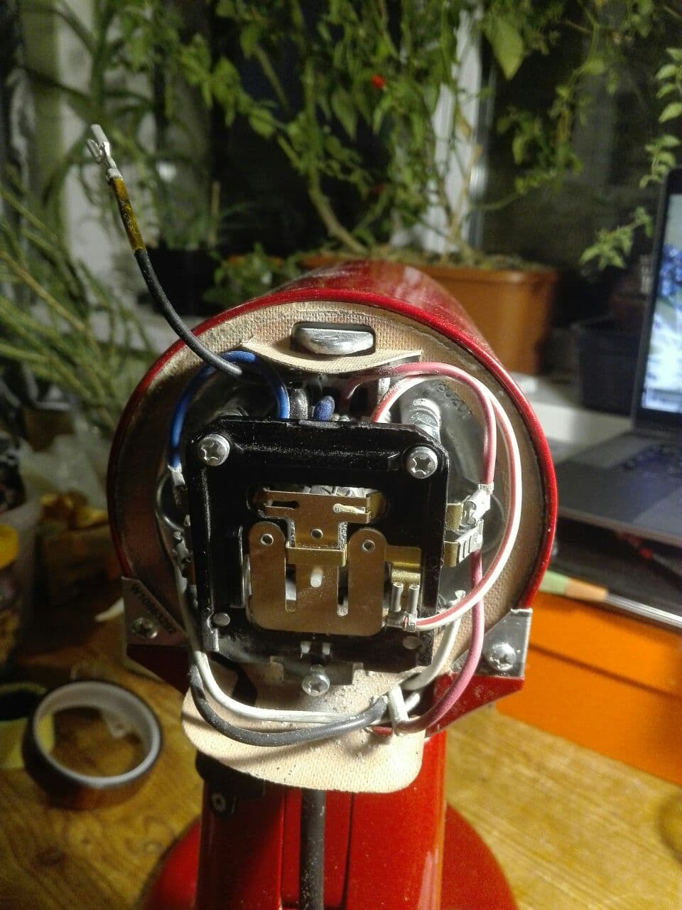
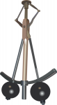
Here I should make a digression, these mixers have ability to maintain constant RPM under different load. I was surprised when I learn how do they do that. One of the main component comes right from the steam engine era, it’s centrifugal governor which is placed on the shaft of the motor, here it is:
Yellow thing is the governor itself, black cylinders highlighted with green – weights, central pin stroked with blue is a pin which provides feedback to control plate. It works simple, the more RPM motor have the more pin extends.
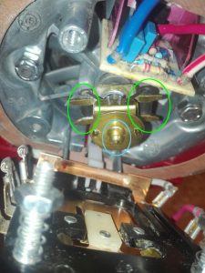
Next component is so called control plate, in fact it has simple main switch and a T shaped contact. The main switch just break circuit when you move switch lever to off. T-contact plate just shorts contacts on a plate in 3 different configuration. The white tab on a picture above is a dielectric tab on T-contact, governor’s central pin pushes this tab and changes which contacts are closed on control plate. Here is control plate from the other side:

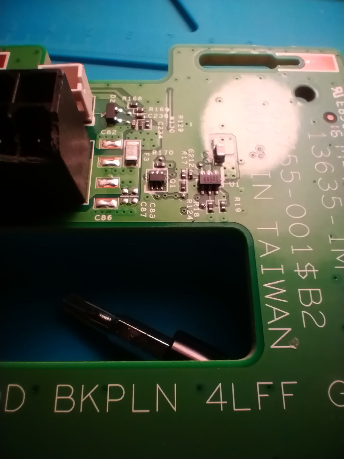
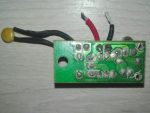
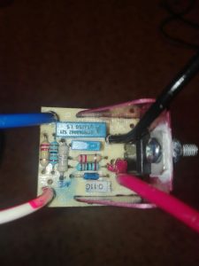
And the last component is a phase control board, it’s basically dimmer if you google for ‘dimmer circuit’ you will find the same scheme as used in phase control board with one exception, usually dimmers have variable resistor for smooth regulation, phase control board has resistors network in which resistors shorts by control board in 3 different configuration. You can see it behind top edge of contral board on the picture above and on closeup photo on picture below:
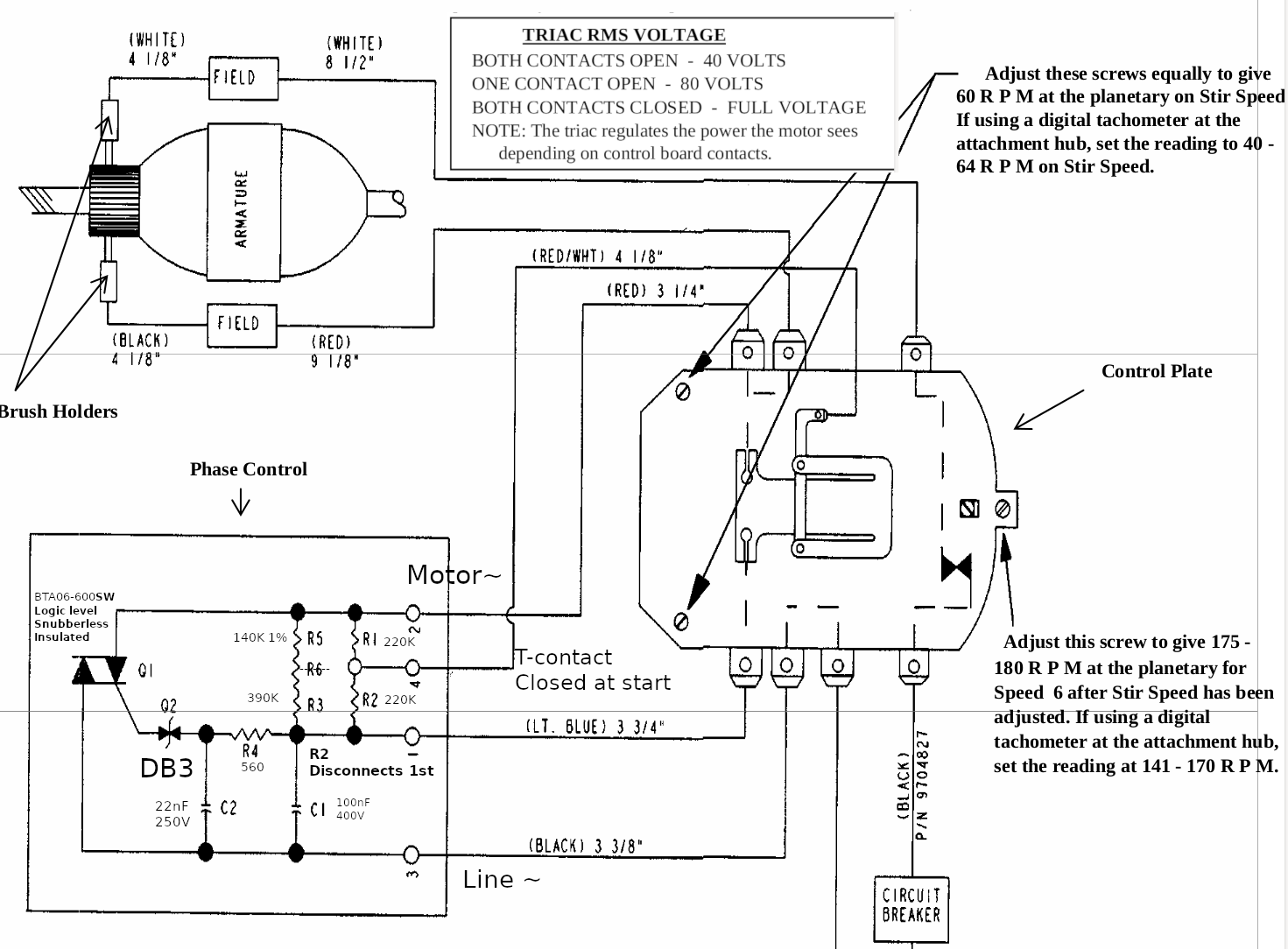
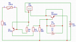
So, how its work together? Here is schematic from repair manual with comments and nominals added by me:

As I sad before control plate can be in 3 different states:
The first: the motor has too low RPM or doesn’t turn at all. T-contact fully closed, it shorts resistor network (R1, R2, R3, R5) completely and feeds motor with almost full sine wave (DIAC Q2 opens at around of 30V, so the start of the wave is chopped a little bit)
The third: the motor has too much RPM. T-contact fully opened, resistors network has maximum resistance, phase control board feeds motor with minimum amount of energy (manual says that it should provide 40V RMS, I don’t understand why it’s true for both 110V and 220V version, but looks like it is).
The second: this state is somewhere in between too low RPM and too much RPM, control board shorts R1, equivalent resistance is ((R5+R3)* R2)/(R5+R3+R2), manual says that it should provide 80V RMS.
The more RPM motor have, the more central pin of centrifugal governor extents, the more it shift T-contact. When T-contact shifting, it opens circuit with bottom contact first and with upper contact next (check schematic above). When you select mixer’s speed you change distance between control plate and governor, the more distance it has the faster motor should spins to get equilibrium between the first and the third states.
Finally I can tell about my issue.
Usually when phase control is broken mixer doesn’t cho-cho at all or doing it on max speed, my story was slightly different, it had near 120 constant RPM on the first 3 speeds, next speed or two increased RPM to the maximum, and other speeds did nothing.
When I saw schematic, I was pretty sure that I just need to replace DIAC. In circuits like this, if something works wrong in 99 cases of 100 it caused by broken semiconductor. When TRIAC failed it usually stays open or shorted (motor shouldn’t run at all or run at full speed).
I changed DIAC but nothing changed, motor had RPM above nominal, but not the maximum. RPM was enough to extent governor’s central pin to the maximum and open both contacts on control plate.
The next suspect was TRIAC, here is only two semiconductors, if one of them is OK, the other one is broken, right? Wrong. I tried two different TRIACs without success. BTA12-600SW (it has the same characteristics like original one. Logic level gate, gate’s current 10mA , snuberless, but rated for 12A instead of 6A) and BTA06-600CW ( it isn’t logic level and had gate current around 35mA, it produced visible sparks during re-commutations on control plate, so don’t use it).
What should be suspected next? Capacitors? Both had less than 5% difference of capacitance from their nominals. I tried other capacitors, RPM of motor changed, but not significantly (in theory failed capacitors may have noticeable different capacity under high voltage, but I tested them with low voltage LCR meter).
After that I started to go crazy, I even de-solder every resistor, but they had correct values.
I spent near 3 days trying to find what’s wrong.
I had a lot of theories: failed resistor which heats when voltage applied and changes its resistance, semi-broken wires, semi-broken motor etc.
I even found a topic in which people had the same issue, but no one find the solution: https://www.electronicspoint.com/forums/threads/kitchenaid-mixer-phase-control-board-problem.241021/page-2
Soon after I started my experiments, I found that everything works as expected when I put R4 with increased value, but I wanted to find why circuit which had right elements didn’t work as it should.
At the end of the third day I gave up. I tried to replace every resistor, every capacitor in circuit and it didn’t helped, I tried to solder wires in parallel with existent,
In the end I decided to put 3.6KOhm R4 instead of original 560Ohm.
Here is my observations:
- Manuals says that you can check phase control by putting sheet of non conductive material (like papper) between T-contact and contact which it touches, if it’s OK it should provide around 40V, but I got 50V. When I lovered voltage to 40V I got response from control plate regulation.
- Motor starts spinning at around 9V DC.
- Coils of stator has resistance of 7.8 Ohm each, rotor has resistance near 4 Ohm between nearest contacts, resistance of motor (between red and white wire) near 40 Ohm.
- Circuit is sensible to element’s values, even when I tried to put capacitors with the same value I got slightly different RPM. My circuit has 1% R5, old scheme from manual has 3 resistors in series, usually this approach used when resistors have breakdown voltage less than voltage drop on them or when you want to use few cheap 5% 10% resistors instead of precise one.
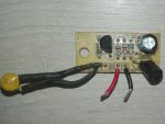
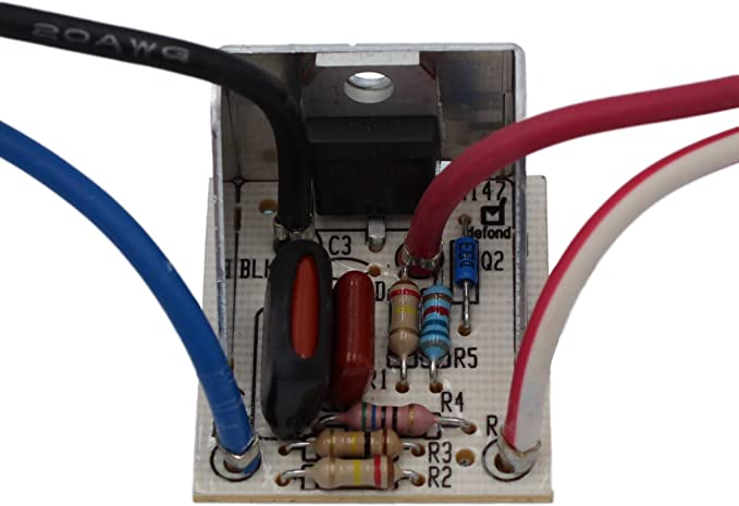
- Probably phase control boards with different part numbers more stable. I found photos of others boards and saw that resistors have values different from values that observed. Here is an example from amazon:
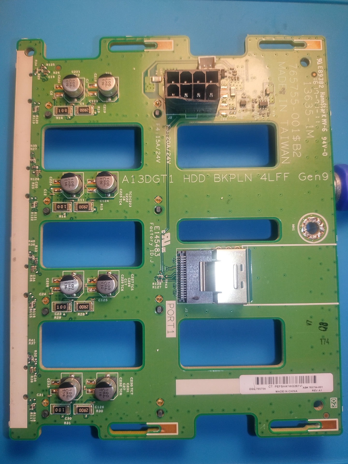
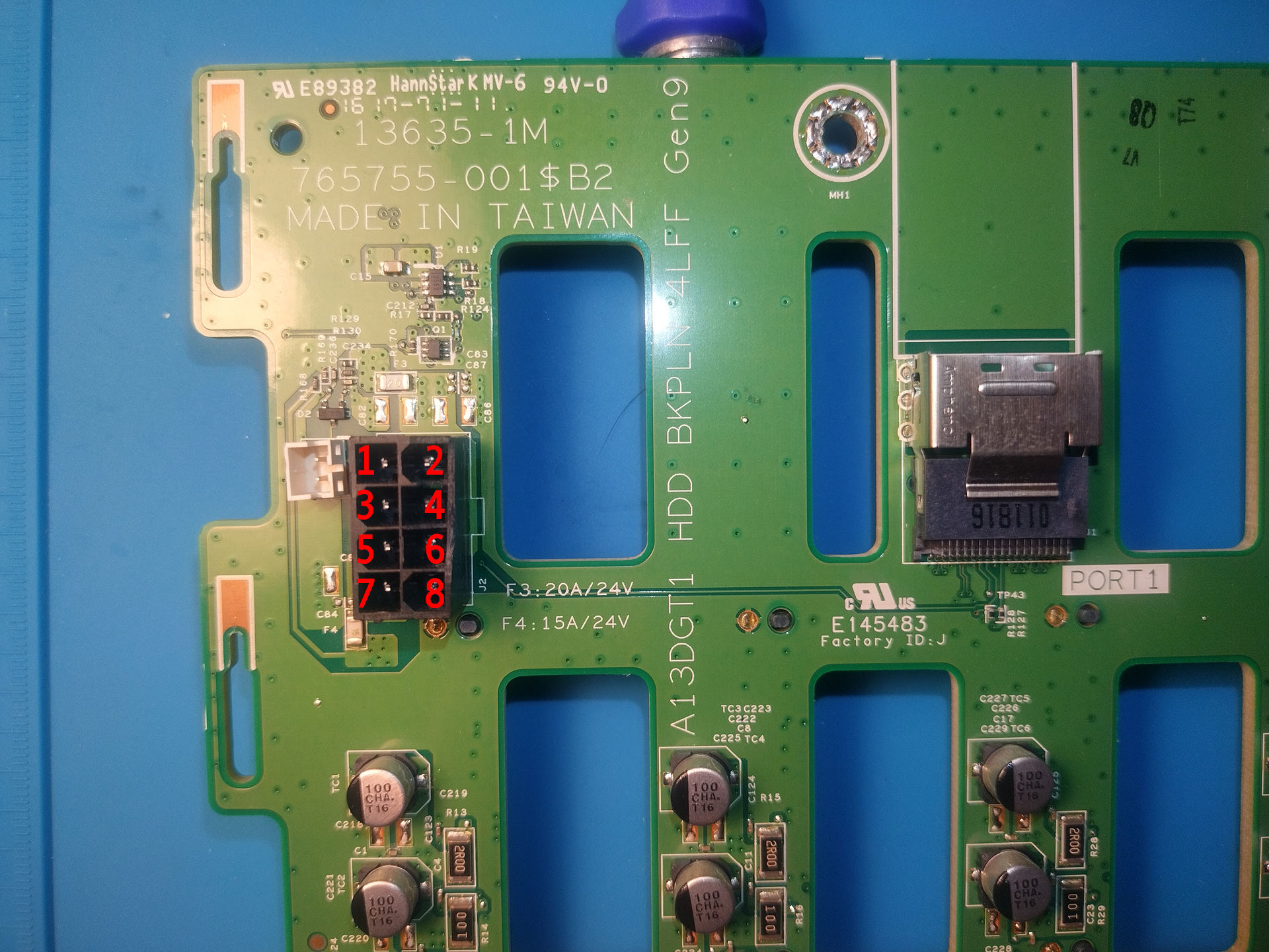 I used multimeter to just poke around the board and find traces from power to SAS power connectors, also I used photos of HP 822606-001 10 pin to 8 Pin connector, just to get a clue about 2 unknown pins.