I have ender 5 which come with creality 1.1.5 board with one little surprise, Marlin’s linear advance doesn’t work on it (klipper seems not to be happy too).
The reason is TMC2208 drivers which are in default stealthChop mode which doesn’t work well with rapid speed and direction changes.
TMC2208 is highly configurable in comparison to old drivers like A4988, but it utilizes half-duplex serial interface. Also it has default configuration stored in OTP (one time programming memory) which again may be changed via serial interface. So, here is two options, connect TMC2208 to onboard microcontroller and let Marlin/Klipper to configure TMC2208 or change OTP.
It’s not so easy to find spare pin on this board (at least I thought so), so I decided to change OTP register.
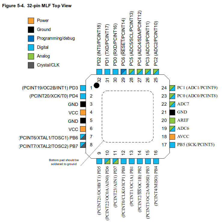
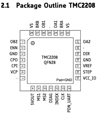
Serial interface is exposed on PIN14 (PDN_UART) of TMC2208 chip:

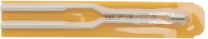
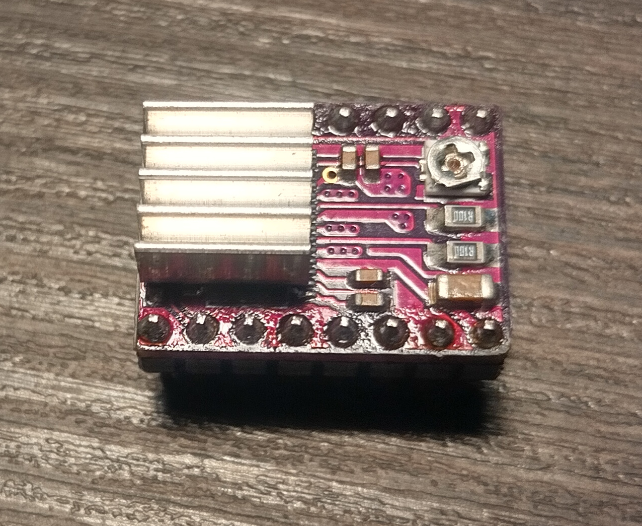
On popular stepstick type drivers which looks like this:
This pin is exposed and easily available, but it’s not the case. On Creality 1.1.5 board these drivers integrated.
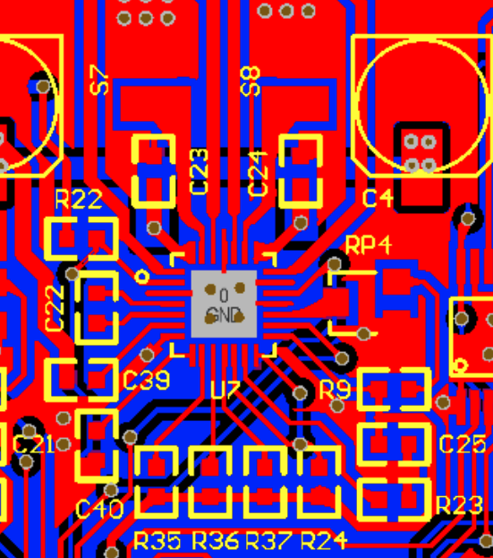
I didn’t found the schematic for revision 1.1.5, but I’ve found PCB view of older revision. I’ve visually compared traces, vias, elements and designates around driver and found them very similar if not the same.
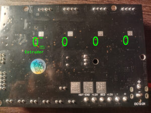
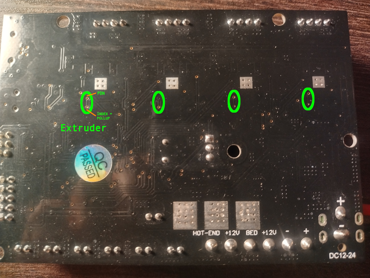
There is PCB view of extruder’s driver:
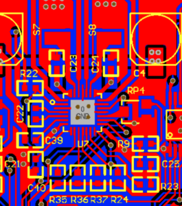
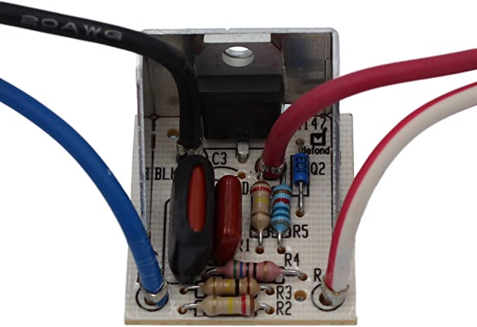
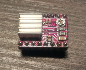
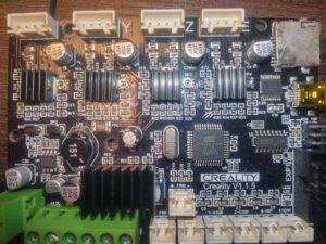
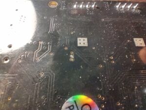
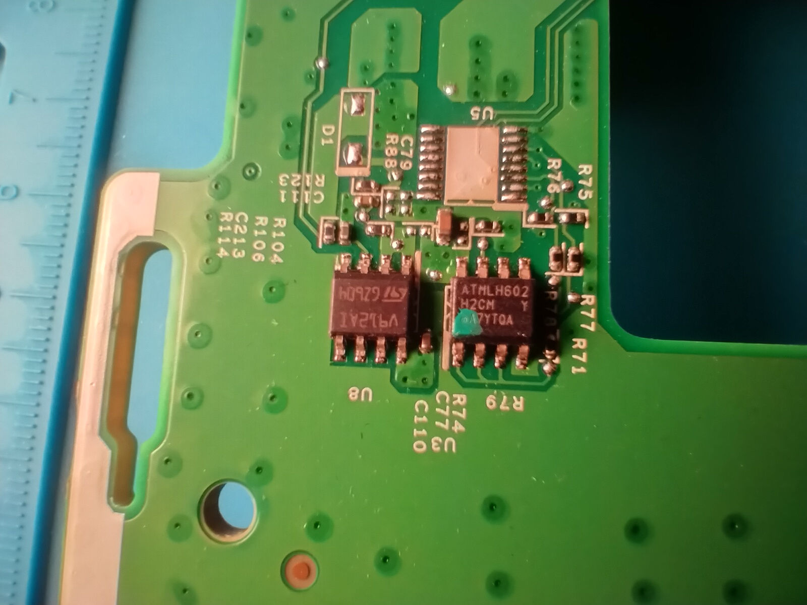
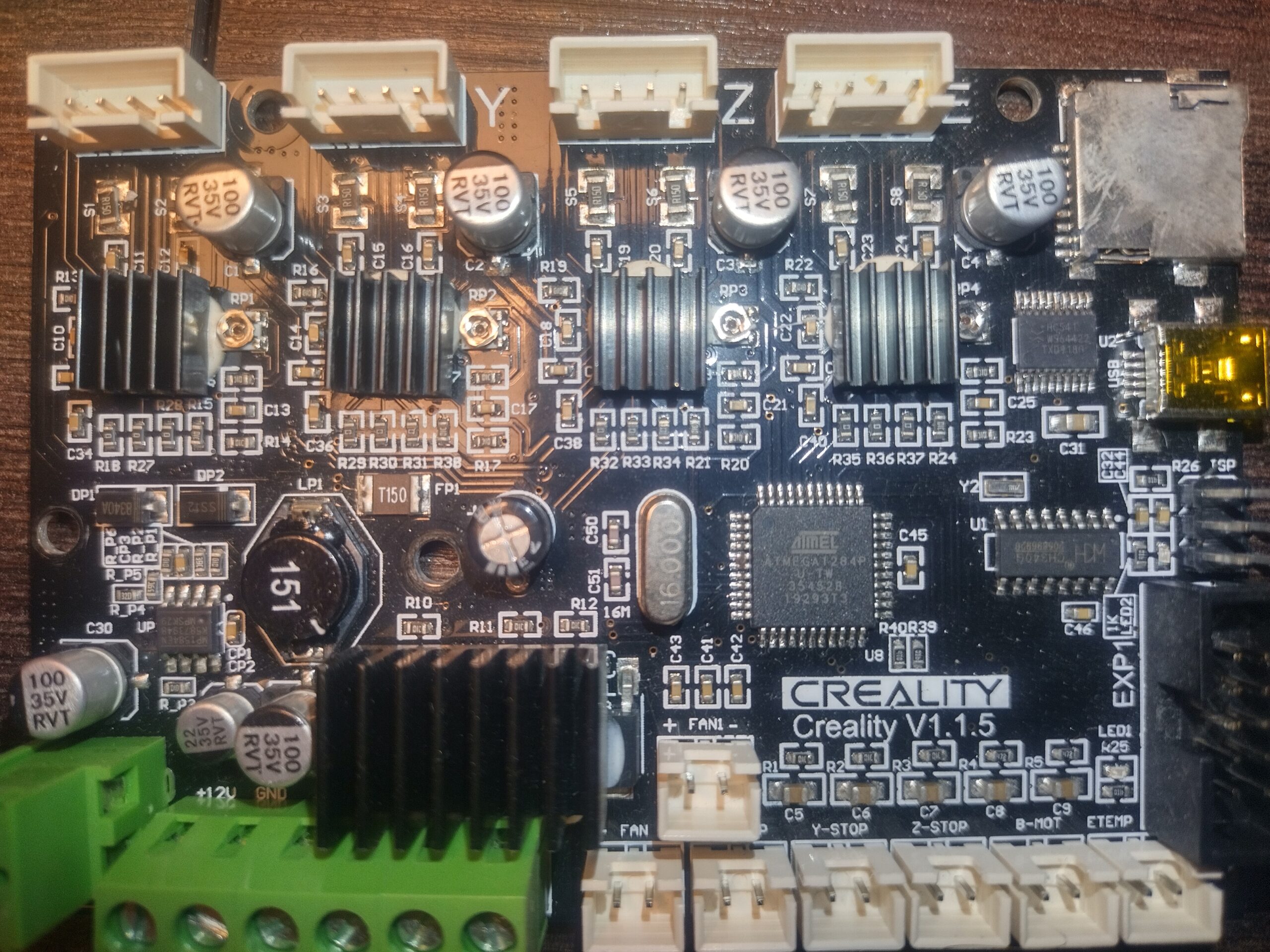
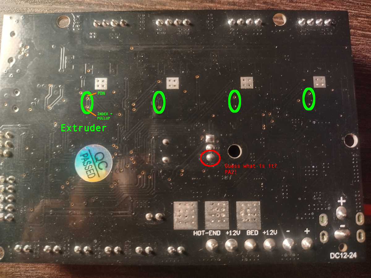
And there is a photo of board I have:
The needed PIN 14 is connected to PIN12 and 10K pull-up resistor.
To change OTP register I needed half-duplex serial and I had three most obvious options out of my head:
- Use usb to serial adapter and join TX and RX lines
- Use separate controller and do bing bang thing
- Use onboard controller and just upload an arduino sketch to do the same (or even use TMC2208Stepper lib to just write OTP register)
I had no spare arduino around and wasn’t sure that will be able to get access to Marlin’s calibration stored in EEPROM and decided to use the first option (it didn’t work well and here is few different reason why which I will write at the end).
First you need ScriptCommunicator to send commands to TMC2208 from there: https://sourceforge.net/projects/scriptcommunicator/
Next, you need to get TMC2208.scez bundle from there: https://github.com/watterott/SilentStepStick/tree/master/ScriptCommunicator
Download them somewhere, they will be used later.
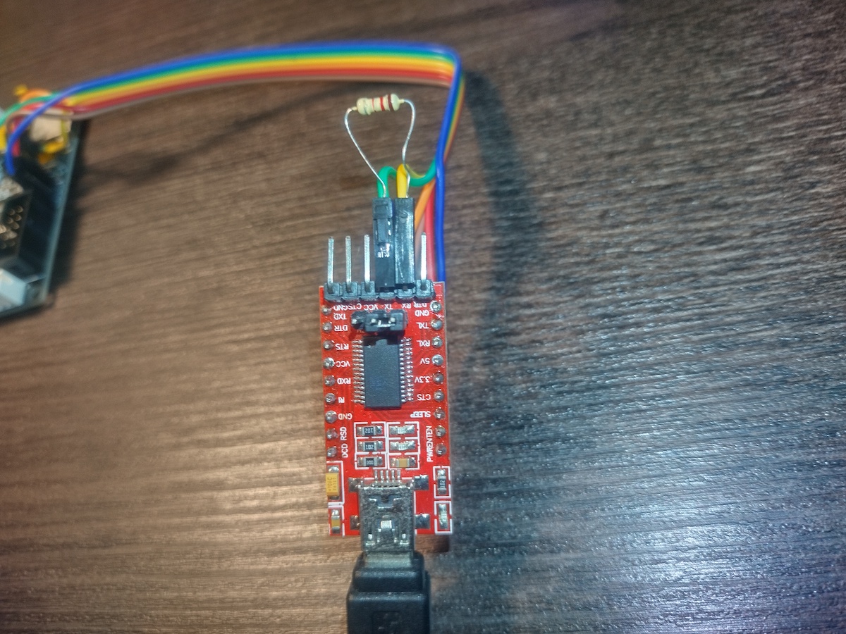
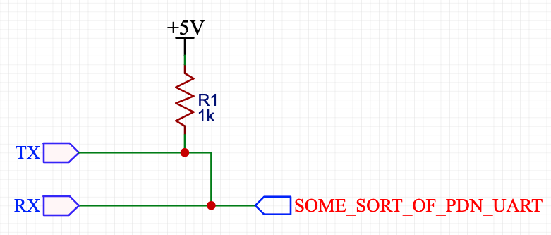
The solution for making half-duplex from usb to serial adapter which is in top of google result looks like that:
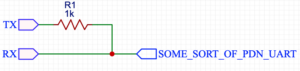
And here is my initial implementation:

Resistor is just pushed into headers which are connected to RX and TX, only wire connected to RX is used to communicate with TMC2208.
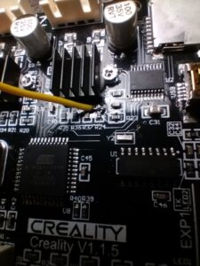
My first idea was to solder wire to R24 (I need to enable spreadCycle only for extruder’s driver) and use usb to serial adapter like this:
The whole construction (5V and GND were connected to ISP header’s pins 2 and 6 respectively):

When everything ready, there is time to open TMC2208.scez, I used the version for linux, so for me it was command like:
/PATH/TO/ScriptCommunicator.sh /PATH/TO/TMC2208.scez
But unfortunately it didn’t work. Each time I hit connect button I got a message “Sending failed. Check hardware connection and serial port.” First I tried to lower connection speed (TMC2208 automatically detects baudrate, 115200 was configured in TMC2208.scez), but without positive result. Next I was checking all the connections between FTDI, resistor and TMC chip – no success. Un-pluging VCC from FTDI and powering board with external PSU – no connection.
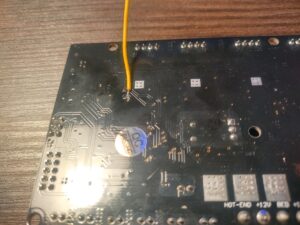
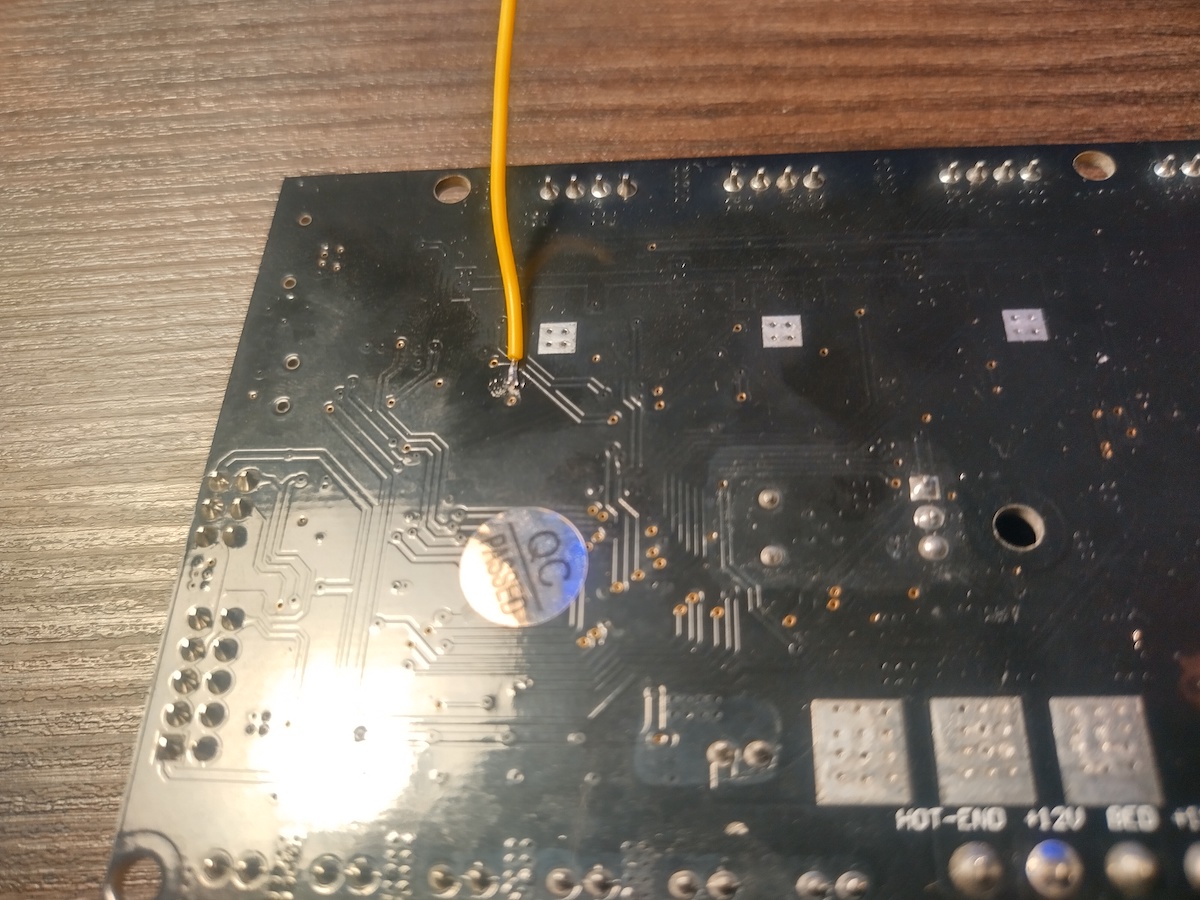
I started to think what can went wrong, the fact that old board revision for A4988 drivers looks pretty similar made me think that creality just put new chip in place of old one and here is obvious candidate INDEX PIN(12) which is connected to PDN. According to datasheet INDEX is digital output, so if it is push-pull, it will definitely mess with serial communication. Only option to fix it is to cut trace between them and solder wire directly to PDN. Luckily it’s just two layer board, so needed trace can be easily located on the back side:
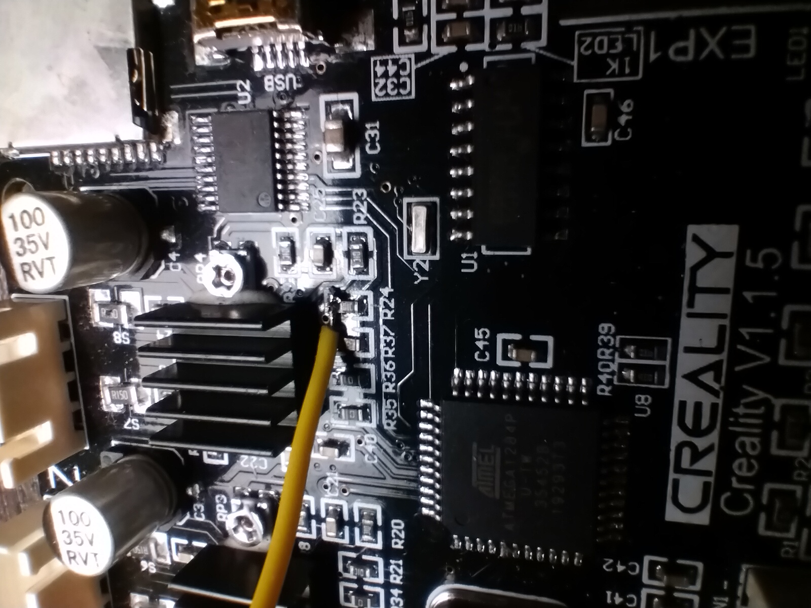
Cut like that:
And solder wire. Wire should be thin and soft otherwise there is a risk to peal off trace completely. Also it’s worth to check that here is no connectivity between wire and R24 after soldering:
I thought that I would finally be able to configure TMC, but to my surprise only change I observed was an checksum error message which I got time to time instead of “Sending failed”.
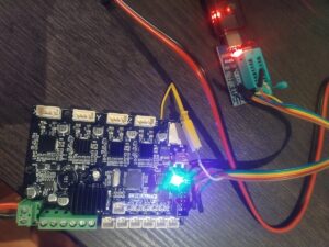
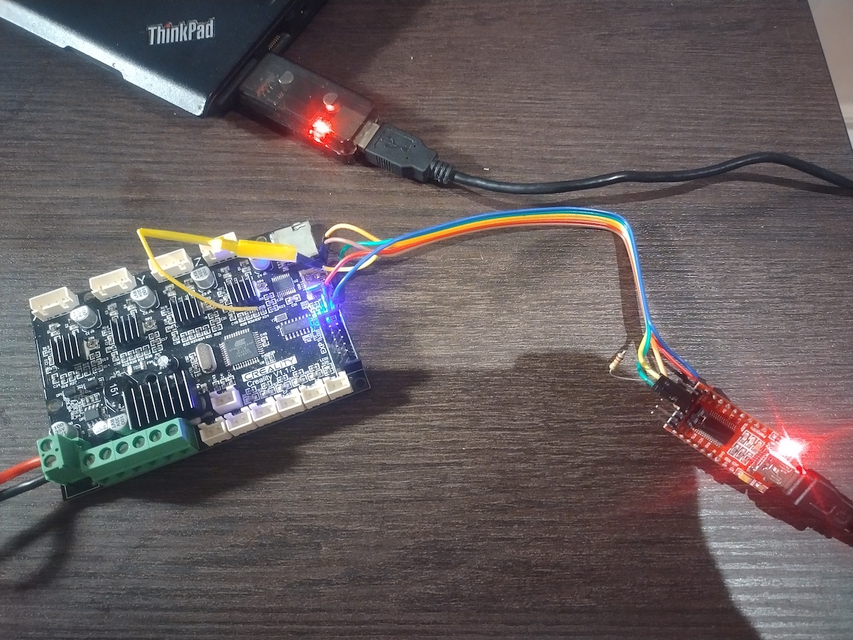
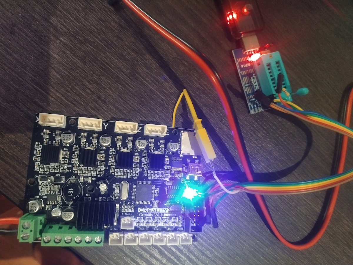
It was around 1:30 after midnight and I almost gave up, when recalled in the very last moment that I have CH341 based programmer. I give it a try and finally it worked:

Only additional change I made, I powered board from external supply, because it was easier than searching for 5V on programmer:
Next to change of OTP (step by step video may be foun there).
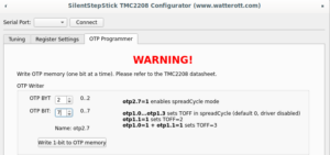
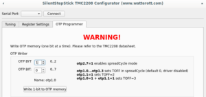
OTP bits can be changed once, that action is irreversible additional attention is needed there.
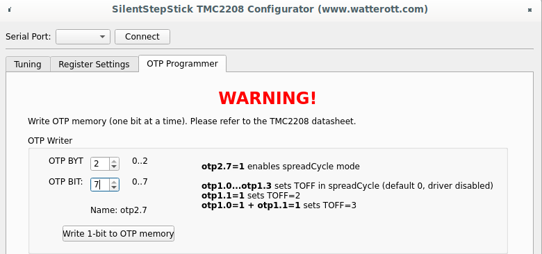
On “OTP Programmer” tab the byte #2 bit #7 should be written to enable spreadCycle mode. After that driver goes to disabled state, until “duration of slow decay phase” is configured to some value other than 0. For me it’s still opaque which value should be written, the SilentStepStick configurator suggests value 3, the same value used as default for stealthChop mode. Without having better ideas I wrote the same, first 4 bits of byte #1 controls duration, to write value 3, bit #0 and bit #1 should be written.
Complete sequence is below:

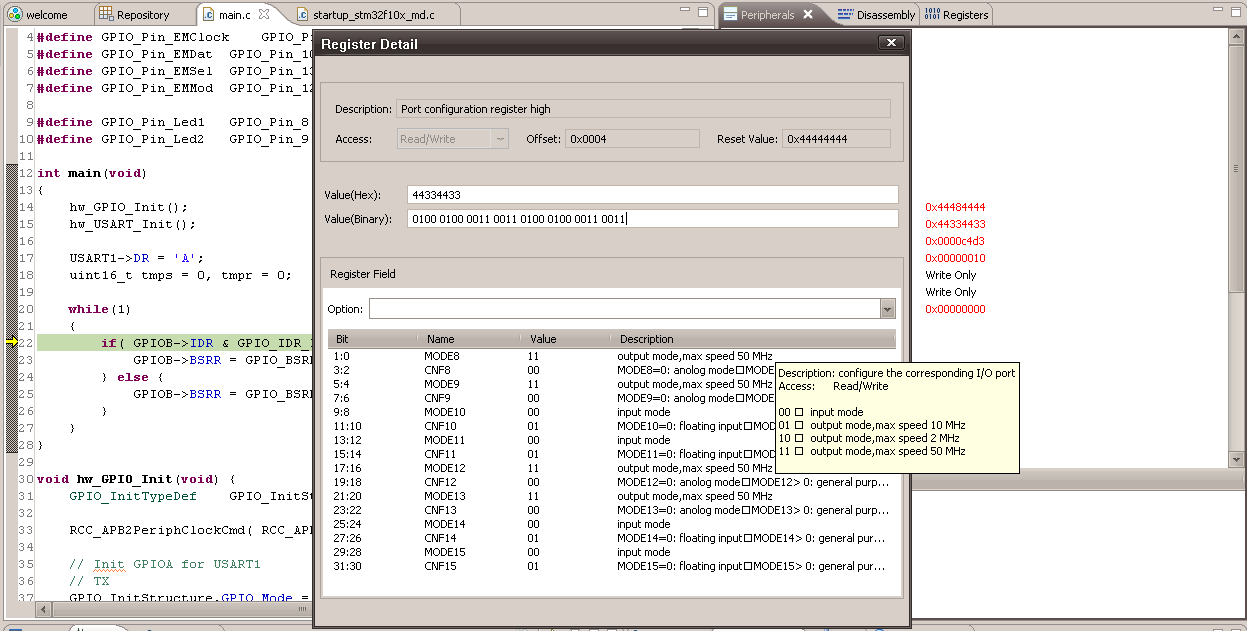
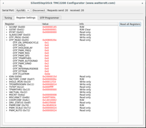
To make sure that OTP configured correctly, it’s needed to click “Read all Registers” button on “Register Settings” tab (not sure why on my screenshot I have OTP_PWM_GRAD equals 2 probably I made screenshot after writing only byte #1 bit #1):
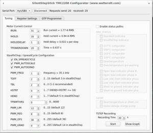
Or disconnect and connect to driver again, “Tuning” tab should have enabled spreadCycle and TOFF set to 3:
PS
Looking back, I see that here is not so much sense in changing OTP in that way or doing it at all.
First making half-duplex serial just by connecting TX and RX with 1k resistor seems wrong. Atmel’s app not AVR947 suggest that it should looks like that:

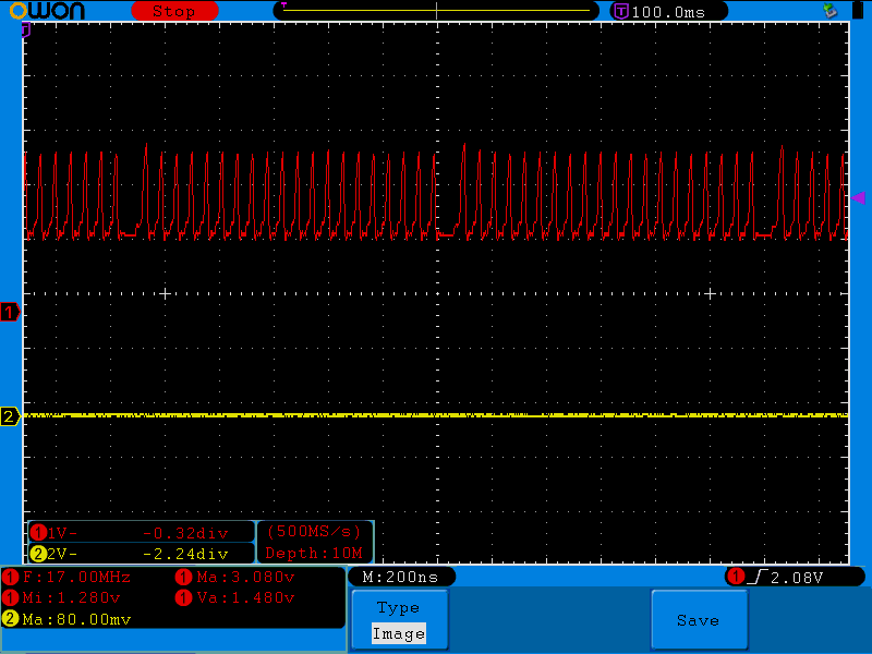
Which makes more sense and explains strange voltage around 2.8V I saw on PDN pin when I was troubleshooting FTDI. Possible explanations why FTDI didn’t work for me is that CH341 has different threshold/voltage levels or has pull-up or my FTDI was partially damaged after series of unfortunate incidents.
Next if for some reason OTP should be changed, it’s easier to use MISO, MOSI or SCK pin from ISP pin header and make arduino sketch.
And finally, there I found that board has partially populated 3 PIN footprint, unused pin connected to pin #35 (PA2) of atmega installed on the board. Without bltouch it’s the easiest option to have constant connection between controller and driver, which allows to use dynamic configuration. Even more with klipper it’s possible (but don’t know why) to have constant connection to each driver and even have bltouch by using SCK, MOSI, MISO (bye sdcard), BEEPER and PA2:

So far I have no bltouch, so even with configure OTP I’m going to solder a wire from PA2 to PDN just to have an option adjust driver configuration on the fly.
Thank for reading.
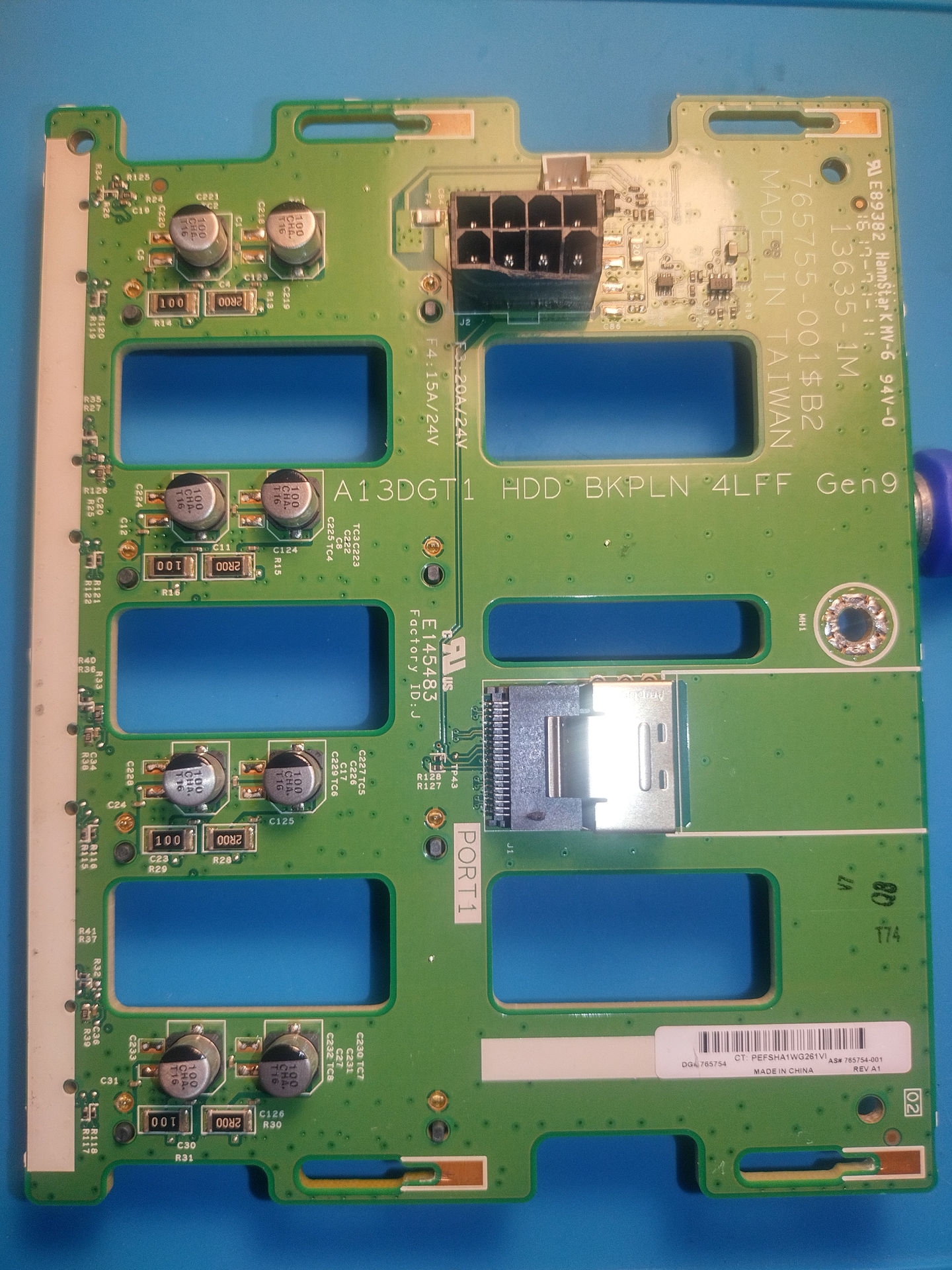
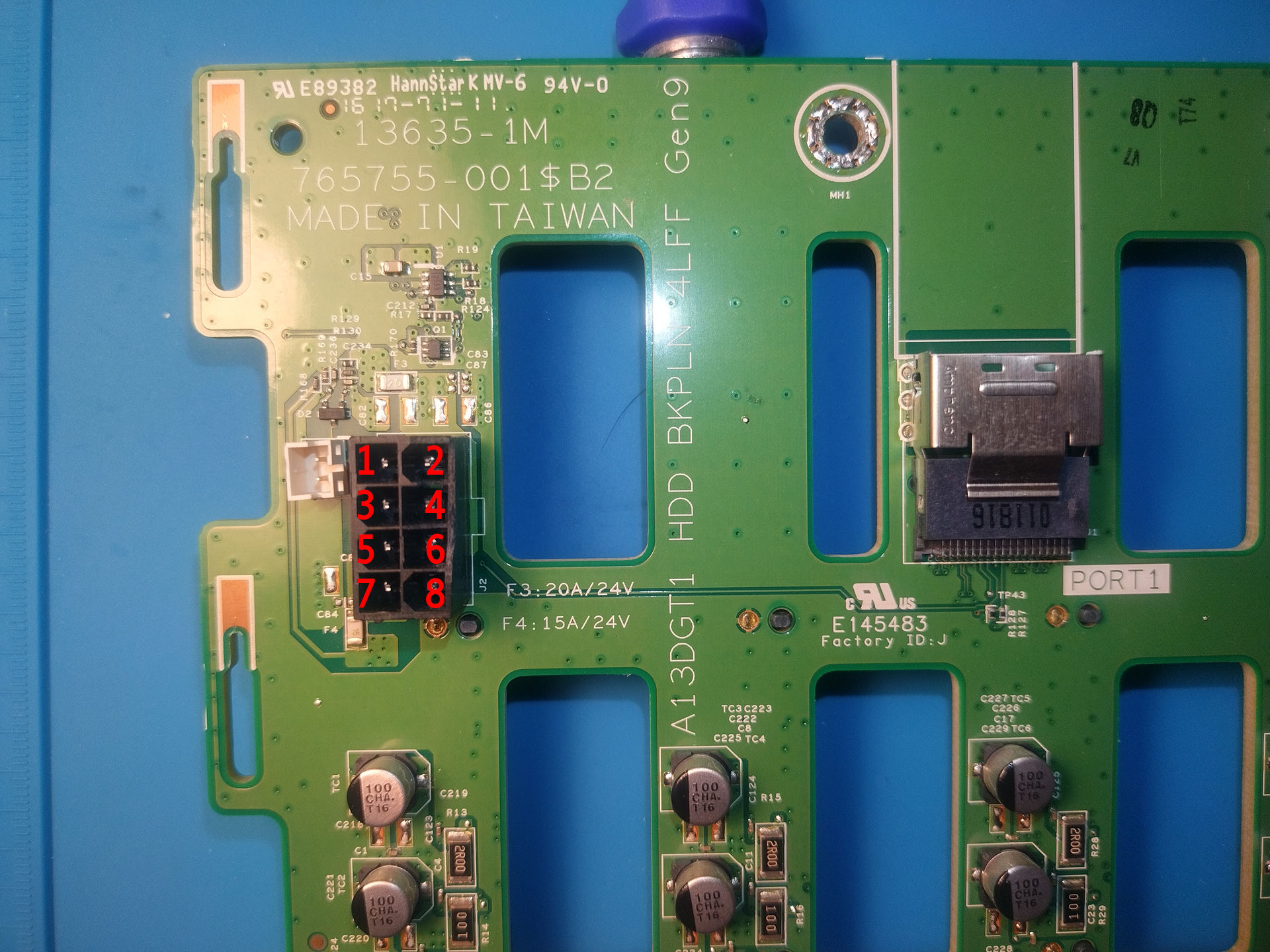 I used multimeter to just poke around the board and find traces from power to SAS power connectors, also I used photos of HP 822606-001 10 pin to 8 Pin connector, just to get a clue about 2 unknown pins.


 It’s a story how I spent thee days troubleshooting 9 elements circuit when 7 of them are passive. I didn’t found what’s wrong, but fixed it.