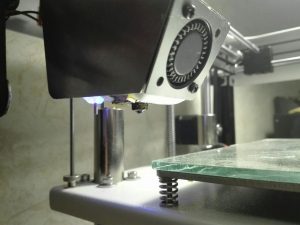
How to pass host device to podman container in user mode using podman-compose

One of the main ideas of containerization is a way to achieve repeatable, hassle-free results. So, when I see headlines that podman gives the same experience and supports docker-compose like deployments (or even provides socket for native docker-compose), I expect that I can grab someone else’s docker-compose file, run $ podman-compose up and enjoy working installation of something. But it’s a trap.

In theory, if you leave service state management out of the equation, it works, but only if the payload doesn’t need access to devices, privileged ports, and you don’t need to organize interpods file sharing or sharing files between the host and pods.

Nevertheless, from time to time when I install a new host with the intention to use containers, I give podman a try as the “new shiny better” alternative to docker. I allocate time (like one evening), and if I’m unable to make it work as I need, I purge it and fall back to docker.

The last time I wanted to run prind in podman, my idea was:

  1. Create separate user
  2. Add it to dialout and video groups on the host system
  3. Run services in user-mode with podman-compose

Looks simple, right? But not in the case of podman.
First of all, device pass-thru doesn’t work in user mode, so if you want to use podman’s --device option, or device: section of compose file, you have to run it under root, which immediately wipes out a major part of podman’s advantages.
Second, podman uses user namespaces, uids:gids which  you see in a container not the same as in a host system. Because of that you may have user root in container which started by regular user, but in fact uids:gids will be offset to a host system by values configured in /etc/{subuid,subgid}, which means that even you have video group in the container, it will be different from the video group that the host system user may be a member of.
Because of that, my first two steps of the plan don’t work out of the box.

To counter that, quite recently, podman has an elegant and beautiful solution: you should add a group named keep-groups to the container with the --group-add option. So, here it is? You just add the group keep-groups to the groups section of the compose file? End of the story? Everything works as expected and everyone is happy? Nope!

For some reason it doesn’t work (at least in debian’s podman-compose 1.0.6-1~bpo12+1). But before this masterpiece was born, the same effect may be achieved with --annotation run.oci.keep_original_groups=1 and it works with compose. You need to mount volume /dev and add the next section:

services:
klipper:
...
volumes:
- /dev:/dev
annotations:
run.oci.keep_original_groups: 1
...

It makes groups looks weird and counter-intuitive in containers and forbids you adding new groups with `groups:` section, but it’s better than nothing:

print3d@aurora:~$ id
uid=1001(print3d) gid=1001(print3d) groups=1001(print3d),20(dialout),44(video),100(users)
print3d@aurora:~$ podman run --group-add keep-groups -v /dev:/dev -it m5p3nc3r/v4l-utils
✔ docker.io/m5p3nc3r/v4l-utils:latest
Trying to pull docker.io/m5p3nc3r/v4l-utils:latest...
Getting image source signatures
Copying blob 366c4c59e228 done
Copying blob 5843afab3874 done
Copying config 13e86697f5 done
Writing manifest to image destination
Storing signatures
/ # id
uid=0(root) gid=0(root) groups=65534(nobody),65534(nobody),65534(nobody),0(root)
/ # ls -l /dev/{ttyUSB1,video0}
ls: /dev/{ttyUSB1,video0}: No such file or directory
/ # ls -ln /dev/ttyUSB1
crw-rw---- 1 65534 65534 188, 1 Dec 26 15:26 /dev/ttyUSB1
/ # ls -ln /dev/video0
crw-rw---- 1 65534 65534 81, 0 Dec 17 15:01 /dev/video0
/ # v4l2-ctl --list-devices
UVC Camera (046d:0825) (usb-0000:04:00.3-5):
/dev/video0
/dev/video1
/dev/media0

The story of how I spent the evening enableing TMC2208 spreadCycle on Creality 1.1.5 board

I have ender 5 which come with creality 1.1.5 board with one little surprise, Marlin’s linear advance doesn’t work on it (klipper seems not to be happy too).
The reason is TMC2208 drivers which are in default stealthChop mode which doesn’t work well with rapid speed and direction changes.

TMC2208 is highly configurable in comparison to old drivers like A4988, but it utilizes half-duplex serial interface. Also it has default configuration stored in OTP (one time programming memory) which again may be changed via serial interface. So, here is two options, connect TMC2208 to onboard microcontroller  and let Marlin/Klipper to configure TMC2208 or change OTP.
It’s not so easy to find spare pin on this board (at least I thought so), so I decided to change OTP register.

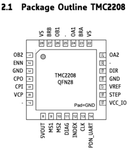
Serial interface is exposed on PIN14 (PDN_UART) of TMC2208 chip:
TMC2208 package

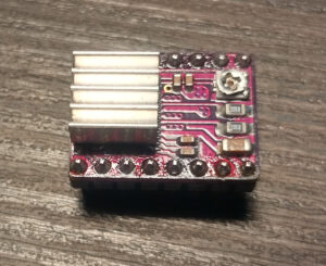
On popular stepstick type drivers which looks like this:

This pin is exposed and easily available, but it’s not the case. On Creality 1.1.5 board these drivers integrated.
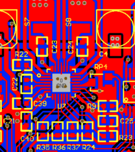
I didn’t found the schematic for revision 1.1.5, but I’ve found PCB view of older revision. I’ve visually compared traces, vias, elements and designates around driver and found them very similar if not the same.

There is PCB view of extruder’s driver:

Extruder's driver

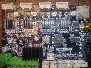
And there is a photo of board I have:

Creality 1.1.5 board

The needed PIN 14 is connected to PIN12 and 10K pull-up resistor.

To change OTP register I needed half-duplex serial and I had three most obvious options out of my head:

  • Use usb to serial adapter and join TX and RX lines
  • Use separate controller and do bing bang thing
  • Use onboard controller and just upload an arduino sketch to do the same (or even use TMC2208Stepper lib to just write OTP register)

I had no spare arduino around and wasn’t sure that will be able to get access to Marlin’s calibration stored in EEPROM and decided to use the first option (it didn’t work well and here is few different reason why which I will write at the end).

First you need ScriptCommunicator to send commands to TMC2208 from there: https://sourceforge.net/projects/scriptcommunicator/
Next, you need to get TMC2208.scez bundle from there: https://github.com/watterott/SilentStepStick/tree/master/ScriptCommunicator
Download them somewhere, they will be used later.

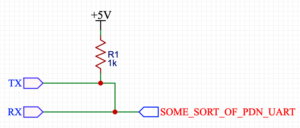
The solution for making half-duplex from usb to serial adapter which is in top of google result looks like that:

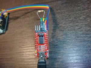
And here is my initial implementation:

Half-duplex implementation
Resistor is just pushed into headers which are connected to RX and TX, only wire connected to RX is used to communicate with TMC2208.
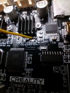
My first idea was to solder wire to R24 (I need to enable spreadCycle only for extruder’s driver) and use usb to serial adapter like this:

1st attempt to solder wire directly to R24

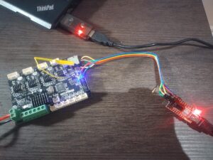
The whole construction (5V and GND were connected to ISP header’s pins 2 and 6 respectively):
FTDI to Creality board connection

When everything ready, there is time to open TMC2208.scez, I used the version for linux, so for me it was command like:

/PATH/TO/ScriptCommunicator.sh /PATH/TO/TMC2208.scez

But unfortunately it didn’t work. Each time I hit connect button I got a message “Sending failed. Check hardware connection and serial port.” First I tried to lower connection speed (TMC2208 automatically detects baudrate, 115200 was configured in TMC2208.scez), but without positive result. Next I was checking all the connections between FTDI, resistor and TMC chip – no success. Un-pluging VCC from FTDI and powering board with external PSU – no connection.

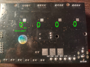
I started to think what can went wrong, the fact that old  board revision for A4988 drivers looks pretty similar made me think that creality just put new chip in place of old one and here is obvious candidate INDEX PIN(12) which is connected to PDN. According to datasheet  INDEX is digital output, so if it is push-pull, it will definitely mess with serial communication. Only option to fix it is to cut trace between them and solder wire directly to PDN. Luckily it’s just two layer board, so needed trace can be easily located on the back side:

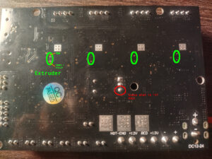
Cut like that:

Back cut PDN to INDEX trace

And solder wire. Wire should be thin and soft otherwise there is a risk to peal off trace completely. Also it’s worth to check that here is no connectivity between wire and R24 after soldering:

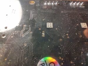
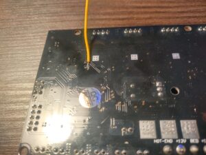
Back of the board, wire soldered to PDN

I thought that I would finally be able to configure TMC, but to my surprise only change I observed was an checksum error message which I got time to time instead of “Sending failed”.
It was around 1:30 after midnight and I almost gave up, when recalled in the very last moment that I have CH341 based programmer. I give it a try and finally it worked:

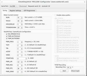
Configurator finally connected
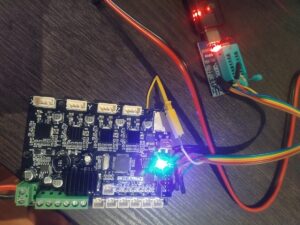
Only additional change I made, I powered board from external supply, because it was easier than searching for 5V on programmer:
CH341 connected to board

Next to change of OTP (step by step video may be foun there).

OTP bits can be changed once, that action is irreversible additional attention is needed there.

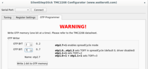
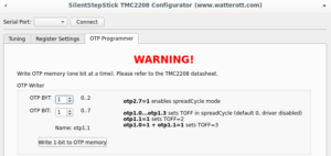
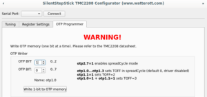
On “OTP Programmer” tab the byte #2 bit #7 should be written to enable spreadCycle mode. After that driver goes to disabled state, until “duration of slow decay phase” is configured to some value other than 0. For me it’s still opaque which value should be written, the SilentStepStick configurator suggests value 3, the same value used as default for stealthChop mode. Without having better ideas I wrote the same, first 4 bits of byte #1 controls  duration, to write value 3,  bit #0 and bit #1 should be written.
Complete sequence is below:

Byte 2 bit 7 Byte 1 bit 1 Byte 1 bit 0

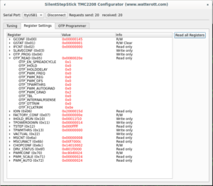
To make sure that OTP configured correctly, it’s needed to click “Read all Registers” button on “Register Settings” tab (not sure why on my screenshot I have OTP_PWM_GRAD equals 2 probably I made screenshot after writing only byte #1 bit #1):

Read OTP bits

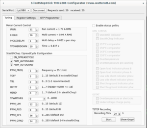
Or disconnect and connect to driver again, “Tuning” tab should have enabled spreadCycle and TOFF set to 3:

Mission complete

PS

Looking back, I see that here is not so much sense in changing OTP in that way or doing it at all.
First  making half-duplex serial just by connecting TX and RX with 1k resistor seems wrong. Atmel’s app not AVR947 suggest that it should looks like that:

Correct half-duplex joining

Which makes more sense and explains strange voltage around 2.8V I saw on PDN pin when I was troubleshooting FTDI. Possible explanations why FTDI didn’t work for me is that CH341 has different  threshold/voltage levels or has pull-up or my FTDI was partially damaged after series of unfortunate incidents.

Next if for some reason OTP should be changed, it’s easier to use MISO, MOSI or SCK pin from ISP pin header and make arduino sketch.

And finally, there I found that board has partially populated 3 PIN footprint, unused pin connected to pin #35 (PA2) of atmega installed on the board. Without  bltouch it’s the easiest option to have constant connection between controller and driver, which allows to use dynamic configuration. Even more with klipper it’s possible (but don’t know why) to have constant connection to each driver and even have bltouch by using SCK, MOSI, MISO (bye sdcard), BEEPER and PA2:

Unused GPIO

So far I have no bltouch, so even with configure OTP I’m going to solder a wire from PA2 to PDN just to have an option adjust driver configuration on the fly.

Thank for reading.

One and a half port charger on TP5100 module

WARNING: Lithium batteries can be extremely dangerous when handled unproperly and lead to fire hazard. Information provided as is, you can use it on your own risk.

Before last holidays I bought cheap Chinese action camera, which came without separate charging station. Camera’s battery could be charged only in camera, charging batteries via which have few cons:

  1. You can damage camera port
  2. If you have more than one battery, you can charge only one at time
  3. You need to watch charging process and change batteries
  4. The last cons depends on camera, but usually compact devices use charger IC with linear regulation and they have low efficiency. If you don’t have access to electrical line and you bound to use power banks, efficiency could be critical.

It’s turned out that a lot of cheap cameras use battery in the same form-factor, thus I decided to share my charger.
I think the most popular solution for single-cell DIY Li-Ion chargers is TP4056 module. It’s almost plug and play solution, usually it have USB port and protection circuit, but it uses linear regulation, so it have low efficiency. Since efficiency is critical for me, I choose TP5100 module, unfortunately it comes without USB port, but it based on buck topology and should be much more efficient than TP4056.
Unfortunately these modules come without USB port (at least I didn’t found TP5100 with USB port).

Thus that project was separated in two main tasks: design carrier board with USB port and design case for charger.

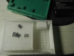
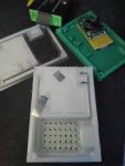
Carrier board is extremely simple, it contains only Micro-USB port and place for TP5100 module.

Case also has simple design, only curlpit which I had – contacts. I made them from nickel plated strips, which I bent once to make it bit thicker:

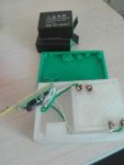
First I had design where contacts should be inserted from side, but it was nearly impossible because of  small gap between side wall and battery holder wall. I redesigned the case in a way when contacts inserted from bottom, un-fortunatelly I didn’t take into account that wires should be soldered from bottom, so supports under contacts should be re-designed or partially melted with solderer as I did it.
To make contacts stiff I glued them in. If they not feet freely into dedicated slots, use solder iron to melt them into slots.
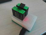
Before gluing them into place, you should be sure that they are long enough and battery fits properly. I supported contacts with fingers during tests. If they have right size, battery should ‘click’ into slot. My batteries stayed in place even when charger with batteries was turned upside-down.

Upper case was printed in with ‘transparent’ plastic, so I can see status led soldered on charger module:

Here is start most interesting part. TP5100 can charge two cells connected to serial, but cells will not be balanced. With a camera I frequently have one partially depleted battery and one fully depleted battery, so I cant charge them in serial configuration without balancer.
Same time it’s not recommended to connect in parallel batteries which discharged un-equally, because current which will flow between batteries will be limited only by resistance of wires and internal resistance of batteries itself.
For myself I decided that it’s acceptable risk because of next reasons:

  1. Batteries like that is not high current, so they should have relatively high internal resistance which will limit current
  2. I especially use thin wires, which have their own noticeable resistance
  3. Contacts also have noticeable resistance
  4. When one battery charges another their potentials aligns. The less difference in voltage the less current flows
  5. I’m planning to connect batteries only when charger powered up, so up to 1A from charger will aligns their potential.

When I did the charger, I connected fully charged battery with battery which was just discharged by camera and measured the current, it was near 0.17A. Batteries like that should be ok at 1C current (0.9A in my case).
I will not agitate anyone to do the same, but I find it ok for myself.

Two more precautions, this charger can be connected only to chragers which are provide more than 1A current. Newer connect that charger to laptop or PC.
TP5100 usually come with maximum charging current set as 1A. If you put 1 battery, it’s a bit more than 1C (0.9A in my case), but I didn’t observed any noticeable warming of battery during charge cycle, so you can set charge current lower or use it with 1A on your own risk.

Here is stl files for  case
Board files: board

Upgrade XTLW3 with MKS Sgen_L & smoothieware

I own XTLW3 3D printer which come with MKS Gen_L  8 bit board and MKS MINI12864 display, out of curiosity I decided to try 32 bit board, one of the cheapest option is MKS Sgen_L  board. Earlier I used marlin firmware on gen_l board, but sgen_l come with smoothieware, so I decided to give it a try.

Looks like the most important advantage of smoothie firmware in comparison with marlin is ability to define your machine settings without re-compiling firmware. You can configure axis resolution, endstops, etc via regular text config file on a sdcard. That approach helps to fix mistakes during configuration or make experiments easily without re-compiling and re-flashing firmware.
Few weeks ago I mounted 3Dtouch sensor (BLtouch’s chinese copy), but I delayed moment of connecting it, anticipating related problems with re-configuring and re-flashing Marlin. Thereby it  was perfect moment to try new firmware.

There MKS provides example config which partially fits my printer, I managed to make it work and here is notes which may be helpful to somebody:

End stops and physical boundaries should be defined, my printer have end stops placed at minimal position for X&Z axis and at maximal position for Y axis. All of them are Normally Opened and connects sense pin to ground when activated, so pull up should be enabled. In XTLW3 hotend nozzle is not above print bed, because end stops misaligned. For me it’s even better, because I made printer dumps small amount of plastic during init procedure paste the table, in that way it doesn’t lie on the bed.
Here is my part of config for end stops and boundaries:

# Limit switch setting
endstops_enable true
soft_endstop.enable
soft_endstop.halt           true   # Whether to issue a HALT state when hitting a soft endstop

## X-axis
alpha_min_endstop 1.29^!
alpha_homing_direction home_to_min
alpha_min           -2
alpha_max           220
soft_endstop.x_min  1
soft_endstop.x_max  220

## Y-axis
beta_max_endstop 1.26^!
beta_homing_direction home_to_max #
beta_min -3
beta_max 224
soft_endstop.y_min          1
soft_endstop.y_max          220

## Z-axis
gamma_min_endstop 1.25^!
gamma_homing_direction home_to_min #
gamma_min -3 #
gamma_max 280 #
soft_endstop.z_min          1            # Minimum Z position
soft_endstop.z_max          285          # Maximum Z position

BTW, you should not exceed 132 characters per line. Also smoothieware uses different naming for axes in comparison with Marlin. For Cartesian based printer aplha means X, beta means Y and gamma means Z.
End stop value is just a pin name (mine placed right on the board), ‘^’ suffix enables pull-up and ‘!’ suffix inverts signal.
End stops configuration can be checked by issuing ‘M119’ g-code in printer’s terminal. You need to achieve all endstops to be reported as ‘0’ when they are not triggered and  ‘1’ when they are all triggered, ie:

X_min:1 Y_max:1 Z_min:0 pins- (X)P1.29:1 (Y)P1.26:1 (Z)P1.25:0 Probe: 0

Here you can see that X and Y end stops was triggered in opposition with  Z which was open.
You need to specify your homing direction in direction where your end stops are placed. I specified to home Y axis to max, because I had end stop at max position in contrast to other axis.
alpha/beta/gamma_min/max – options used to specify physical dimensions of axes. My printer has square rectangular table specified by two points (1,1; 220,220), but head can move besides that coordinates.
When head homed by XY it home outside of table space:

So when I set negative values or values larger than actual table, I just shifted origin, to make it placed on a corner of print table.
Soft limits just set boundaries for G<X> movement codes, they prevents movements which may damage  printer.

I don’t want to make a saga from that post, so I will  continue in the next posts.