WARNING: Lithium batteries can be extremely dangerous when handled unproperly and lead to fire hazard. Information provided as is, you can use it on your own risk.
Before last holidays I bought cheap Chinese action camera, which came without separate charging station. Camera’s battery could be charged only in camera, charging batteries via which have few cons:
- You can damage camera port
- If you have more than one battery, you can charge only one at time
- You need to watch charging process and change batteries
- The last cons depends on camera, but usually compact devices use charger IC with linear regulation and they have low efficiency. If you don’t have access to electrical line and you bound to use power banks, efficiency could be critical.
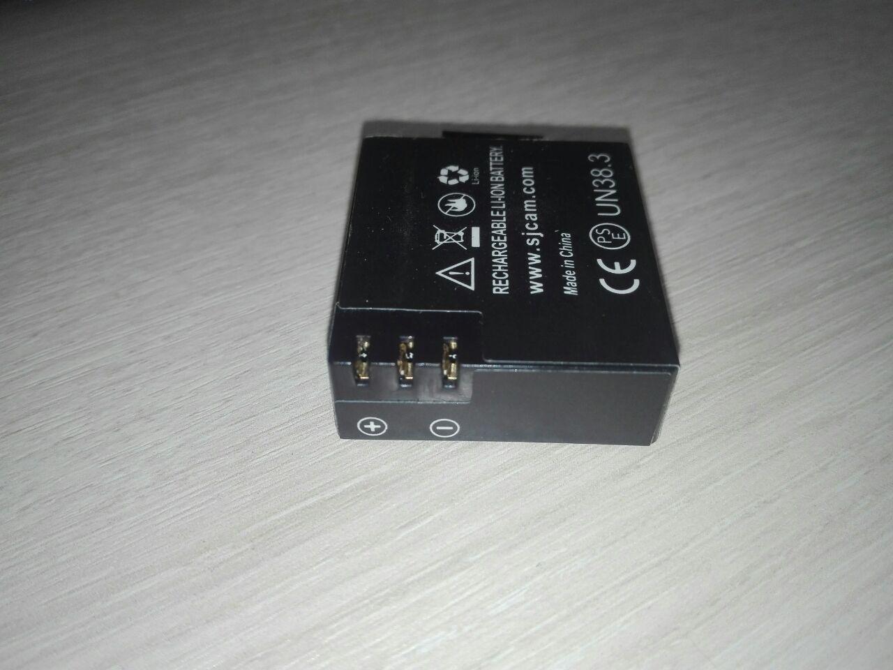 It’s turned out that a lot of cheap cameras use battery in the same form-factor, thus I decided to share my charger.
I think the most popular solution for single-cell DIY Li-Ion chargers is TP4056 module. It’s almost plug and play solution, usually it have USB port and protection circuit, but it uses linear regulation, so it have low efficiency. Since efficiency is critical for me, I choose TP5100 module, unfortunately it comes without USB port, but it based on buck topology and should be much more efficient than TP4056.
Unfortunately these modules come without USB port (at least I didn’t found TP5100 with USB port).
Thus that project was separated in two main tasks: design carrier board with USB port and design case for charger.
Carrier board is extremely simple, it contains only Micro-USB port and place for TP5100 module.
Case also has simple design, only curlpit which I had – contacts. I made them from nickel plated strips, which I bent once to make it bit thicker:
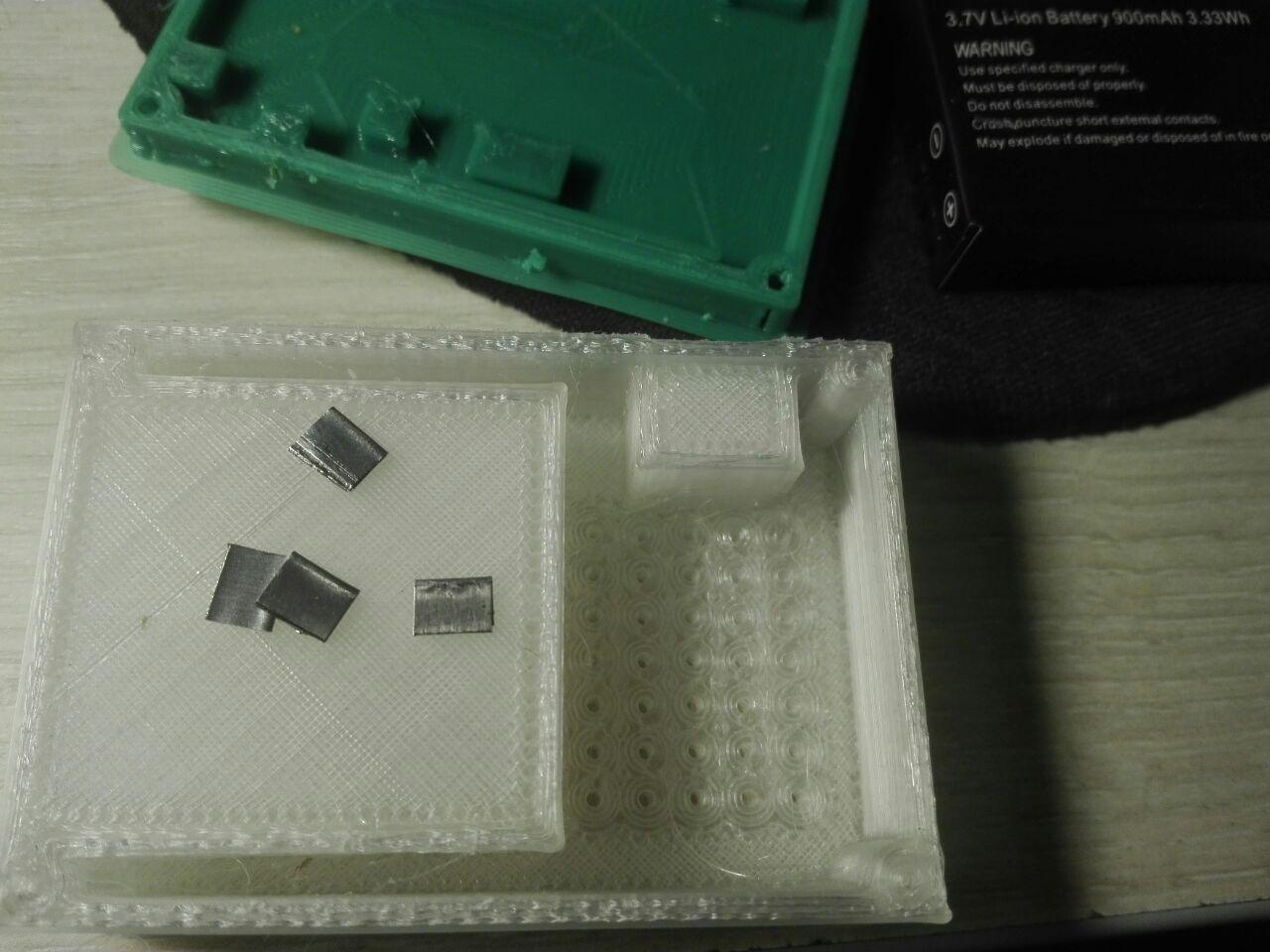

 First I had design where contacts should be inserted from side, but it was nearly impossible because of small gap between side wall and battery holder wall. I redesigned the case in a way when contacts inserted from bottom, un-fortunatelly I didn’t take into account that wires should be soldered from bottom, so supports under contacts should be re-designed or partially melted with solderer as I did it.
To make contacts stiff I glued them in. If they not feet freely into dedicated slots, use solder iron to melt them into slots.
Before gluing them into place, you should be sure that they are long enough and battery fits properly. I supported contacts with fingers during tests. If they have right size, battery should ‘click’ into slot. My batteries stayed in place even when charger with batteries was turned upside-down.
Upper case was printed in with ‘transparent’ plastic, so I can see status led soldered on charger module: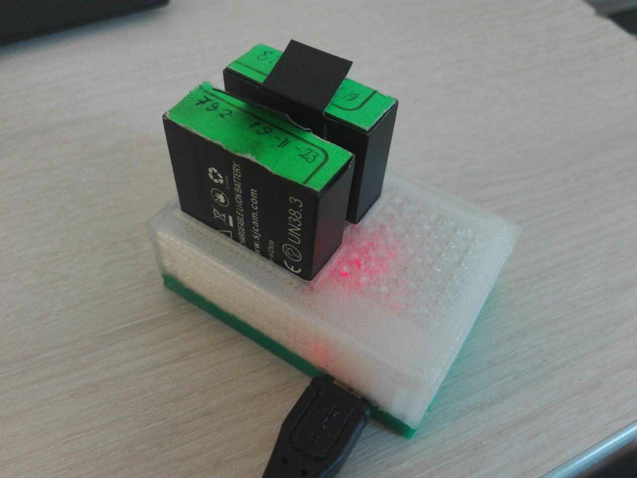
Here is start most interesting part. TP5100 can charge two cells connected to serial, but cells will not be balanced. With a camera I frequently have one partially depleted battery and one fully depleted battery, so I cant charge them in serial configuration without balancer.
Same time it’s not recommended to connect in parallel batteries which discharged un-equally, because current which will flow between batteries will be limited only by resistance of wires and internal resistance of batteries itself.
For myself I decided that it’s acceptable risk because of next reasons:
- Batteries like that is not high current, so they should have relatively high internal resistance which will limit current
- I especially use thin wires, which have their own noticeable resistance
- Contacts also have noticeable resistance
- When one battery charges another their potentials aligns. The less difference in voltage the less current flows
- I’m planning to connect batteries only when charger powered up, so up to 1A from charger will aligns their potential.
When I did the charger, I connected fully charged battery with battery which was just discharged by camera and measured the current, it was near 0.17A. Batteries like that should be ok at 1C current (0.9A in my case).
I will not agitate anyone to do the same, but I find it ok for myself.
Two more precautions, this charger can be connected only to chragers which are provide more than 1A current. Newer connect that charger to laptop or PC.
TP5100 usually come with maximum charging current set as 1A. If you put 1 battery, it’s a bit more than 1C (0.9A in my case), but I didn’t observed any noticeable warming of battery during charge cycle, so you can set charge current lower or use it with 1A on your own risk.