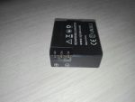
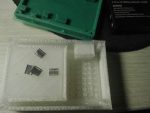
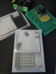
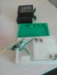
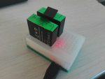
One and a half port charger on TP5100 module

WARNING: Lithium batteries can be extremely dangerous when handled unproperly and lead to fire hazard. Information provided as is, you can use it on your own risk.

Before last holidays I bought cheap Chinese action camera, which came without separate charging station. Camera’s battery could be charged only in camera, charging batteries via which have few cons:

  1. You can damage camera port
  2. If you have more than one battery, you can charge only one at time
  3. You need to watch charging process and change batteries
  4. The last cons depends on camera, but usually compact devices use charger IC with linear regulation and they have low efficiency. If you don’t have access to electrical line and you bound to use power banks, efficiency could be critical.

It’s turned out that a lot of cheap cameras use battery in the same form-factor, thus I decided to share my charger.
I think the most popular solution for single-cell DIY Li-Ion chargers is TP4056 module. It’s almost plug and play solution, usually it have USB port and protection circuit, but it uses linear regulation, so it have low efficiency. Since efficiency is critical for me, I choose TP5100 module, unfortunately it comes without USB port, but it based on buck topology and should be much more efficient than TP4056.
Unfortunately these modules come without USB port (at least I didn’t found TP5100 with USB port).

Thus that project was separated in two main tasks: design carrier board with USB port and design case for charger.

Carrier board is extremely simple, it contains only Micro-USB port and place for TP5100 module.

Case also has simple design, only curlpit which I had – contacts. I made them from nickel plated strips, which I bent once to make it bit thicker:

First I had design where contacts should be inserted from side, but it was nearly impossible because of  small gap between side wall and battery holder wall. I redesigned the case in a way when contacts inserted from bottom, un-fortunatelly I didn’t take into account that wires should be soldered from bottom, so supports under contacts should be re-designed or partially melted with solderer as I did it.
To make contacts stiff I glued them in. If they not feet freely into dedicated slots, use solder iron to melt them into slots.
Before gluing them into place, you should be sure that they are long enough and battery fits properly. I supported contacts with fingers during tests. If they have right size, battery should ‘click’ into slot. My batteries stayed in place even when charger with batteries was turned upside-down.

Upper case was printed in with ‘transparent’ plastic, so I can see status led soldered on charger module:

Here is start most interesting part. TP5100 can charge two cells connected to serial, but cells will not be balanced. With a camera I frequently have one partially depleted battery and one fully depleted battery, so I cant charge them in serial configuration without balancer.
Same time it’s not recommended to connect in parallel batteries which discharged un-equally, because current which will flow between batteries will be limited only by resistance of wires and internal resistance of batteries itself.
For myself I decided that it’s acceptable risk because of next reasons:

  1. Batteries like that is not high current, so they should have relatively high internal resistance which will limit current
  2. I especially use thin wires, which have their own noticeable resistance
  3. Contacts also have noticeable resistance
  4. When one battery charges another their potentials aligns. The less difference in voltage the less current flows
  5. I’m planning to connect batteries only when charger powered up, so up to 1A from charger will aligns their potential.

When I did the charger, I connected fully charged battery with battery which was just discharged by camera and measured the current, it was near 0.17A. Batteries like that should be ok at 1C current (0.9A in my case).
I will not agitate anyone to do the same, but I find it ok for myself.

Two more precautions, this charger can be connected only to chragers which are provide more than 1A current. Newer connect that charger to laptop or PC.
TP5100 usually come with maximum charging current set as 1A. If you put 1 battery, it’s a bit more than 1C (0.9A in my case), but I didn’t observed any noticeable warming of battery during charge cycle, so you can set charge current lower or use it with 1A on your own risk.

Here is stl files for  case
Board files: board

Upgrade XTLW3 with MKS Sgen_L & smoothieware

I own XTLW3 3D printer which come with MKS Gen_L  8 bit board and MKS MINI12864 display, out of curiosity I decided to try 32 bit board, one of the cheapest option is MKS Sgen_L  board. Earlier I used marlin firmware on gen_l board, but sgen_l come with smoothieware, so I decided to give it a try.

Looks like the most important advantage of smoothie firmware in comparison with marlin is ability to define your machine settings without re-compiling firmware. You can configure axis resolution, endstops, etc via regular text config file on a sdcard. That approach helps to fix mistakes during configuration or make experiments easily without re-compiling and re-flashing firmware.
Few weeks ago I mounted 3Dtouch sensor (BLtouch’s chinese copy), but I delayed moment of connecting it, anticipating related problems with re-configuring and re-flashing Marlin. Thereby it  was perfect moment to try new firmware.

There MKS provides example config which partially fits my printer, I managed to make it work and here is notes which may be helpful to somebody:

End stops and physical boundaries should be defined, my printer have end stops placed at minimal position for X&Z axis and at maximal position for Y axis. All of them are Normally Opened and connects sense pin to ground when activated, so pull up should be enabled. In XTLW3 hotend nozzle is not above print bed, because end stops misaligned. For me it’s even better, because I made printer dumps small amount of plastic during init procedure paste the table, in that way it doesn’t lie on the bed.
Here is my part of config for end stops and boundaries:

# Limit switch setting
endstops_enable true
soft_endstop.enable
soft_endstop.halt           true   # Whether to issue a HALT state when hitting a soft endstop

## X-axis
alpha_min_endstop 1.29^!
alpha_homing_direction home_to_min
alpha_min           -2
alpha_max           220
soft_endstop.x_min  1
soft_endstop.x_max  220

## Y-axis
beta_max_endstop 1.26^!
beta_homing_direction home_to_max #
beta_min -3
beta_max 224
soft_endstop.y_min          1
soft_endstop.y_max          220

## Z-axis
gamma_min_endstop 1.25^!
gamma_homing_direction home_to_min #
gamma_min -3 #
gamma_max 280 #
soft_endstop.z_min          1            # Minimum Z position
soft_endstop.z_max          285          # Maximum Z position

BTW, you should not exceed 132 characters per line. Also smoothieware uses different naming for axes in comparison with Marlin. For Cartesian based printer aplha means X, beta means Y and gamma means Z.
End stop value is just a pin name (mine placed right on the board), ‘^’ suffix enables pull-up and ‘!’ suffix inverts signal.
End stops configuration can be checked by issuing ‘M119’ g-code in printer’s terminal. You need to achieve all endstops to be reported as ‘0’ when they are not triggered and  ‘1’ when they are all triggered, ie:

X_min:1 Y_max:1 Z_min:0 pins- (X)P1.29:1 (Y)P1.26:1 (Z)P1.25:0 Probe: 0

Here you can see that X and Y end stops was triggered in opposition with  Z which was open.
You need to specify your homing direction in direction where your end stops are placed. I specified to home Y axis to max, because I had end stop at max position in contrast to other axis.
alpha/beta/gamma_min/max – options used to specify physical dimensions of axes. My printer has square rectangular table specified by two points (1,1; 220,220), but head can move besides that coordinates.
When head homed by XY it home outside of table space:

So when I set negative values or values larger than actual table, I just shifted origin, to make it placed on a corner of print table.
Soft limits just set boundaries for G<X> movement codes, they prevents movements which may damage  printer.

I don’t want to make a saga from that post, so I will  continue in the next posts.

Lenovo battery hack and whitelist at the same time

Recently I’ve got x230 laptop and have a plan to change buggy Intel Centrino 6205 adapter to something like Atheros, also I decided that it’s worth to have ability to use x220 like batteries, just in case.
To achieve that, I needed to flash patched firmware for EC controller (thinkpad-ec project) and modified bios (1vyrain project), but it was confusing, what should go first? Firstly I didn’t realised that thinkpad-ec flashes only EC firmware, it looked like EC mod will update bios to newer version than supported by 1vyrain, same time 1vyrain would update bios to version newer than supported by thinpkad-ec.
Finally, here is how to have EC mod together with patched BIOS on x230 laptop:
1. BIOS should be old enough to be compatible with  1vyrain and thinpkad-ec, at 2020-03-22 it should be not newer than 2.60 (1vyrain has requirements of more older bios than thinkpad-ec, requirements for 1vyrain patch can be found here)  otherwise it should be downgraded as described here.
2. Make bootable device with thinkpad-ec image, in BIOS set boot mode to ‘Legacy’ and update EC firmware.
3. Make bootable device with 1vyrain image, in BIOS set boot mode “UEFI only”, disable “Secure boot” and update BIOS.

In my case I ended with BIOS version 2.77 EC version 1.14.

STM32Cube FW_F1 V1.8.0 package breaks HAL time source init

As a hobby I’m working on a growbox controller which based on stm32 MCU. Yesterday I got STM32Cube MCU package update, as many times before I just upgraded package and project to latest version, as result firmware started to stuck in assert_failed().

It happens during call of SystemClock_Config() (defined in main.c) which in turn calls  HAL_RCC_ClockConfig(), which in turn calls HAL_InitTick(uwTickPrio) at Drivers/STM32F1xx_HAL_Driver/Src/stm32f1xx_hal_rcc.c:947:

...
  /* Update the SystemCoreClock global variable */
  SystemCoreClock = HAL_RCC_GetSysClockFreq() &gt;&gt; AHBPrescTable[(RCC-&gt;CFGR &amp; RCC_CFGR_HPRE) &gt;&gt; RCC_CFGR_HPRE_Pos];
 
  /* Configure the source of time base considering new system clocks settings*/
  HAL_InitTick(uwTickPrio);
 
  return HAL_OK;
}

When it happens uwTickPrio still have invalid interrupt priority, which is defined in Drivers/STM32F1xx_HAL_Driver/Src/stm32f1xx_hal.c:80:

...
/** @defgroup HAL_Private_Variables HAL Private Variables
  * @{
  */
__IO uint32_t uwTick;
uint32_t uwTickPrio   = (1UL &lt;&lt; __NVIC_PRIO_BITS); /* Invalid PRIO */
HAL_TickFreqTypeDef uwTickFreq = HAL_TICK_FREQ_DEFAULT;  /* 1KHz */
...

Only one place where uwTickPrio can be updated is ./Drivers/STM32F1xx_HAL_Driver/Src/stm32f1xx_hal.c:234:

__weak HAL_StatusTypeDef HAL_InitTick(uint32_t TickPriority)
{
  /* Configure the SysTick to have interrupt in 1ms time basis*/
  if (HAL_SYSTICK_Config(SystemCoreClock / (1000U / uwTickFreq)) &gt; 0U)
  {
    return HAL_ERROR;
  }
 
  /* Configure the SysTick IRQ priority */
  if (TickPriority &lt; (1UL &lt;&lt; __NVIC_PRIO_BITS))
  {
    HAL_NVIC_SetPriority(SysTick_IRQn, TickPriority, 0U);
    uwTickPrio = TickPriority;
  }
  else
  {
    return HAL_ERROR;
  }
 
  /* Return function status */
  return HAL_OK;
}

But this function is redefined in ./Core/Src/stm32f1xx_hal_timebase_tim.c:42:

HAL_StatusTypeDef HAL_InitTick(uint32_t TickPriority)
{
  RCC_ClkInitTypeDef    clkconfig;
  uint32_t              uwTimclock = 0;
  uint32_t              uwPrescalerValue = 0;
  uint32_t              pFLatency;
 
  /*Configure the TIM4 IRQ priority */
  HAL_NVIC_SetPriority(TIM4_IRQn, TickPriority ,0);
 
...

And doesn’t contain proper uwTickPrio initialization, as result it’s called with invalid TickPriority  and fails into assert_failed() during HAL_NVIC_SetPriority(TIM4_IRQn, TickPriority ,0) call.

How to just send logs from files to graylog2

That solution allows to read logs from file and just send them to remote syslog/graylog server. Logs will not influent on current syslog settings, you won’t need to filter them out of any syslog facility (like local7), all you need – the rsyslog (I’ve used v8).

My task was to send logs which wrote by java application (if I’m right log4j was used), they were rotated by logrotate with truncation, so few specific options were added.
I replaced %APP-NAME% in rsyslog’s template(RSYSLOG_SyslogProtocol23Format) to be able differentiate from which files log messages were read.

As for me, it’s better to write logs in format which allow them to be parsed easily or send them right to remote location , but if you need to do it quickly without modification of application it’s appropriate solution. Just copy config below in file like  /etc/rsyslog.d/99-graylog.conf and modify TARGET.ADDRESS, TARGET.PORT, app_ tag and File setting according to your environment.

module(load="imfile")

template(
name="SyslogProtocol23Format_modified" type="string"
string="<%PRI%>1 %TIMESTAMP:::date-rfc3339% %HOSTNAME% %syslogtag%%$.suffix% %PROCID% %MSGID% %STRUCTURED-DATA% %msg%\n"
)

ruleset(name="sendToLogserver") {
action(type="omfwd" Target="TARGET.ADDRESS" Port="TARGET.PORT" Template="SyslogProtocol23Format_modified")
}

ruleset(name="app_logs") {
set $.suffix=re_extract($!metadata!filename, "(.*)/([^/]*)", 0, 2, "unknown.log");
call sendToLogserver
stop
}

input(
type="imfile"
File="/var/log/app_logs/*.log"
Tag="app_"
Ruleset="app_logs"
freshStartTail="on"
addMetadata="on"
)

In my case application wrote multi-line log messages, so startmsg.regex was used. Also logs were rotated by logrotate with truncate method, additional option reopenOnTruncate was used. So my input section looked like:

input(
type="imfile"
File="/var/log/app_logs/*.log"
Tag="app_"
Ruleset="app_logs"
freshStartTail="on"
addMetadata="on"
startmsg.regex="^[0-9]{4}-[0-9]{2}-[0-9]{2} "
reopenOnTruncate="on"
)

Fixing startup error of STMCubeMX on linux

After STMCubeMX was upgraded from version 4 to version 5, it can’t start. I’ve tried to reinstall it, but without result. Last messages in console after application stuck looks like:

2019-01-24 21:03:54,692 [INFO] PluginManage:339 - Loaded plugin projectmanager (category:projectmanager,tabindex:3)
2019-01-24 21:04:38,908 [ERROR] IntegrityCheckThread:90 - Cannot obtain updater plugin
2019-01-24 21:04:38,909 [INFO] IntegrityCheckThread:94 - End integrity checks thread
2019-01-24 21:04:38,909 [INFO] ThirdPartyDb:263 - Close Third Party DataBase File (/home/bob/.stm32cubemx/plugins/thirdparty/db/thirdparties_db.xml)

Same time java processes looks like:

bob 20652 102 1.5 5841340 127888 pts/3 Sl+ 21:03 2:41 java -jar STM32CubeMX
bob 20653 0.0 0.0 0 0 pts/3 Z+ 21:03 0:00 [STM32CubeMX] <defunct>

On the st forum I’ve found solution which had helped me, if you change tabindex parameter of com/st/microxplorer/plugins/tools/Plugin.properties in tools.jar to 6, STMCube will start to work.
Here is modified tools.jar

Fixing Gutenberg error “The editor has encountered an unexpected error”

After update to WP 5, I’ve faced with next issue, I’ve couldn’t add new post or edit existed. Looks like error happens because of misconfigured nginx and when new ‘Gutenberg’ editor is active (which is true by default for wordpress 5.0 and above).

Earlier I had nginx location / configured in next manner:

location / {
    try_files $uri $uri/ /index.php?$args;
}

Same configuration can be found on wordpress codex page:

And on nginx recipe page:

The issue caused by question sign in try_files directive, when $args is empty, index.php is called like this: “/index.php?”. Solution is simple:

$is_args
    “?” if a request line has arguments, or an empty string otherwise

After I changed location / block like this:

location / {
    try_files $uri $uri/ /index.php$is_args$args;
}

The problem is gone.

How to configure redmine service via terraform with persistent storage on amazon ECS

First of all, I have very little experience of AWS and terraform, so it can be obviously for them who have enough experience, but it definitely saved me a lot of time if I found article like that early.

It wasn’t simple to figure out how to run redmine container on ECS.
The main problem was – persistent storage. Redmine suppose that it have persistent disk storage which remain the same between service restarts. If you have your docker host it’s simply to map hipervisor’s directory inside of the container, but when your docker nodes can be added and removed dynamically you can lost data on disk which was generated by app.
Amazon provide few ways to have persistent storage such as S3, EBS or EFS.

By nature S3 is a storage which accessibly over http, so if your app haven’t integration with S3 API it can’t be used (except when you mount S3 via fuse fs for example).
EBS is a remote block storage, so you need to connect block device to docker host, mount it and map inside container before you will be able to use it.
EFS by nature is just a NFS.

I wanted to find solution which will be most natural as possible. I wanted to keep docker and redmine image untouched (ie avoid of additional plugins/scripts/packages installation). So, I decided not to use S3, because it need something like s3fs to make S3 storage available for redmine.
I decided not to use EBS, because I’ve found reports when EBS stuck attached to host and can’t be re-attached to another host until initial host reboots.
EFS looked perfect, it could be mounted from different hosts, it kept data during application/hypervisor life cycles. Moreover, even if I didn’t find a simple way to use EFS, only thing I needed was nfs-common package.

I was lucky, because at the Aug of 2018 amazon announced support of docker volumes and docker volumes plugins, docker itself can mount NFS inside containers since version 17.06 (I couldn’t found it in the change log, but if you google it, you will found a lot of references to that). So, it was exactly what I wanted, I faced only with one cons – lack of documentation. I needed to use terraform for redmine configuration and its documentation didn’t specify how to exactly pass driver_opts to docker volume configuration, so here is solution:

First you need to specify mount point in task-definition.json

"mountPoints":[
     {
       "sourceVolume": "redmine_storage",
       "containerPath": "/usr/src/redmine/files"
     }
 ]

And here is volume block from from terraform code for volume specification:

volume {
    name = "redmine_storage"
    docker_volume_configuration {
        scope         = "task"
        driver      = "local"
        driver_opts = {
            "type" = "nfs"
            "device" = "${var.efs_dns}:/"
            "o" = "addr=${var.efs_dns},nfsvers=4.1,rsize=1048576,wsize=1048576,hard,timeo=600,retrans=2"
        }
 }
}

That’s all.
Code above is a part of redmine module, which have input variable efs_dns , so you can put your EFS address here if you configured it manually.

PS
Here you can find redmine S3 plugin, but I wanted to migrate existing redmine, so it looked like a lot of work, because I needed to modify rdemine’s DB and put files on S3 in manner which that plugin expects, so I decided that S3 not an option.

How to block IP ranges of specified autonomous system

If you want to prohibit access to your host for specified AS, you can use solution below. I made it some time ago, when I found out, that mail.ru hunting for hosts which help to bypass telegram censorship. It’s not perfect because I didn’t make much effort to it. Whois can return sub-networks and networks to which they belong in same response, so ipset set can contain duplicated ranges. Change ‘AS47764’ to AS which you want to block, ‘input_drop’ is an ipset set name.

ipset create input_drop hash:net comment
for i in $(whois -h whois.radb.net -- '-i origin AS47764' | grep 'route:'|cut -d : -f 2)
do
ipset add input_drop $i comment mail.ru
done
iptables -A INPUT -m set --match-set input_drop src -m comment --comment "DROP INPUT packets for AS47764" -j DROP

Also, i would recommend that solution, to make ipset rules persistent: https://github.com/BroHui/systemd-ipset-service

Galaxy S3: /efs/prox_cal doesn’t affect calibration settings under LineageOS

Few days ago I replaced front glass on samsung i9300 and flashed LineageOS 14.1. After that I’ve found that proximity sensor stays in triggered state, it may happened because of lack of experience (I’ve used too much UV-glue, so it was everywhere) or because of additional screen protector which been installed. Anyway, always-triggered-proximity-sensor made phone partially usable (you can’t cancel any call without pushing power button few times). I’ve found a lot of articles how to calibrate proximity sensor like this one. More over I’ve found that I shouldn’t do any calculation to update /efs/prox_cal, after auto-calibration /efs/prox_cal updated automatically (at least with kernel that shipped by default), but anyway it didn’t help me. Every reboot calibration  was reseted to zero.

For a first time, I’ve used proximity threshold value to fix proximity sensor, but later I saw that kernel driver read calibration directly from file and SELinux could be a reason why /efs/prox_cal haven’t effect.

Part that read calibration value looks like that:

#define CANCELATION_FILE_PATH "/efs/prox_cal"
...
int proximity_open_calibration(struct ssp_data *data)
{
 int iRet = 0;
 mm_segment_t old_fs;
 struct file *cancel_filp = NULL;
 
old_fs = get_fs();
 set_fs(KERNEL_DS);
 
cancel_filp = filp_open(CANCELATION_FILE_PATH, O_RDONLY, 0666);
 if (IS_ERR(cancel_filp)) {
 iRet = PTR_ERR(cancel_filp);
 if (iRet != -ENOENT)
 pr_err("[SSP]: %s - Can't open cancelation file\n",
 __func__);
 set_fs(old_fs);
 goto exit;
}

I’ve checked logcat and here is it:

05-06 21:29:12.916 3219 3219 W Binder:2377_A: type=1400 audit(0.0:39): avc: denied { read } for name="prox_cal" dev=mmcblk0p3 ino=46 scontext=u:r:system_server:s0 tcontext=u:object_r:efs_device_file:s0 tclass=file permissive=0

Definitely SELinux forbid reading of calibration file, I was surprised that SElinux capable to forbid kernel read call and now I feel a shame because usually I just disable it.

First I wanted to create new policy to allow reading of that file for kernel, but later I’ve found that /efs partition contains other calibration files, for example /efs/gyro_cal_data, I’ve checked security context of that files and found that it differs from /efs/prox_cal, it was u:object_r:sensors_data_file:s0 but prox_cal was created with default for /efs partition context u:object_r:efs_file:s0, so I’ve changed context:

# chcon u:object_r:sensors_data_file:s0 /efs/prox_cal

After that kernel started to load calibration value every boot. Looks like instructions like one mentioned above works for everyone who modified factory shipped prox_cal file with right security context, but I haven’t /efs/prox_cal before and it was created with wrong context.
I hope that story may help someone.