If I had to choose the software that gives me the biggest headache, it would be ArgoCD.
This time, I have to admit it’s not solely an ArgoCD issue – but let’s see.
What’s the most likely course of action for someone who needs to configure SSO login for ArgoCD?
Probably read the documentation for your provider. That’s exactly what I did.
What’s the most crucial part there? Probably the Dex config:
dex.config: | connectors: - config: redirectURI: https://argocd.example.com/api/dex/callback clientID: XXXXXXXXXXXXX.apps.googleusercontent.com clientSecret: XXXXXXXXXXXXX serviceAccountFilePath: /tmp/oidc/googleAuth.json adminEmail: [email protected] type: google id: google name: Google |
What should you expect when the OAuth client and Google service accounts are created, the Dex deployment is patched, and the config is in place?
Probably working SSO, right?
Nope. You should expect the middle finger ArgoCD shows you instead.
You’ll get a blank page and a message in the Dex server logs:
time="2025-06-16T06:52:43Z" level=info msg="dex is not configured"
And when you’ve checked all the configurations, you probably expect that debug logging will help, right?
That’s when ArgoCD shows you the second middle finger:
~ $ /shared/argocd-dex rundex --loglevel debug
INFO[0000] maxprocs: Leaving GOMAXPROCS=2: CPU quota undefined
INFO[0000] ArgoCD Dex Server is starting                 built="2025-04-22T15:31:47Z" commit=82831155c2c1873b3b5d19449bfa3970dab9ce24 namespace=argocd version=v2.14.11+8283115
INFO[0000] Generating self-signed TLS certificate for this session
INFO[0000] Starting configmap/secret informers
INFO[0000] Configmap/secret informer synced
INFO[0000] Loading TLS configuration from secret argocd/argocd-server-tls
INFO[0000] 0xc00055e770 subscribed to settings updates
INFO[0000] dex is not configured
Oh, ArgoCD, why are you so mean?
Let’s check its config:
~ $ /shared/argocd-dex gendexcfg --loglevel debug
INFO[0000] maxprocs: Leaving GOMAXPROCS=2: CPU quota undefined
INFO[0000] Starting configmap/secret informers
INFO[0000] Configmap/secret informer synced
INFO[0000] Loading TLS configuration from secret argocd/argocd-server-tls
INFO[0000] dex is not configured
It’s time to remember that ArgoCD has eight tentacles – so showing up to eight middle fingers shouldn’t be a problem for it.
So, what’s the problem, and why can’t I say it’s solely an issue with ArgoCD or its documentation?
In the case of integration with Google, it says:
 And when you navigate to OpenID Connect using Dex you can notice small detail in example of dex.config:
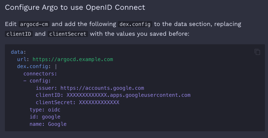
The url key.
And maybe you’ll say, “Ah-ha, it’s definitely a documentation issue – in “OpenID Connect plus Google Groups using Dex” it says:
“Go through the same steps as in OpenID Connect using Dex, except for configuring argocd-cm. We’ll do that later.”
So you think you shouldn’t pay attention to the Dex configuration example—and you’d be wrong.
You just don’t know how to use the documentation.
You shouldn’t skip the overview, where the importance of the url key is clearly emphasized.
Or you should google it and find an example of argocd-cm for the ArgoCD Operator, where a comment clearly says:
# Argo CD's externally facing base URL (optional). Required when configuring SSO
So no, it’s not a problem with the documentation – it’s a problem with those who don’t read the documentation carefully.
Why does the argocd-dex-server just log INFO[0000] dex is not configured when the dex.config is present but the url key is missing?
Well, because…

PS
I used documentation for ‘stable’ release which is 2.14 or 3.0. In the release-3.1 docs (I think that’s the latest now), the example for argocd-cm is fixed and actually includes the url key.