Half year ago i wanted to get in car PSU to charge my smartphone or to power devices like camcoder. I wanted to build powerful power supply, first i tried to build it on chip NCP3155, but has failed. I lurking around to find another chip and found complete module KIS-3R33 based on MP2307 chip. I found it very interesting and cheap, after i got few i started to find way how to change output voltage from 3.3V to 5V. I found many guides how to change Vout, by replacing internal components and all of them ignore the fact, that module have Adjust pin. I wanted to find way how to change Vout without replacing internal components.
KIS-33R3 very similar to typical application:
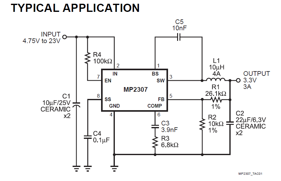
Datasheet give ratio for calculation of Vout depend of R1 and R2:
Vout = 0.925* (R1 + R2) / R2
According to scheme of module that i found into the internet, Adjust pin connected to FB in series with resistor of 3.3kOhm:

R1 = 25.5 kOhm (two 51kOhm resistors in parallel), so it is possible to vary R1 in range 25.5 kOhm – 2.9 kOhm and R2 in range 10 kOhm – 2.48 kOhm it give output range 1.19V – 10.43V. If you need voltage more than 5V, you need to remove zener diode first (D2 on scheme), because this diode limit Vout to 5.1V. Also voltage range of output capacitor (C2 on scheme) is not know, so it is good idea to replace it with capacitor that can handle your output voltage.
I wrote simple calculator for KIS-3R33 that compute resistor that you must connect between Adj pin and GND or Vout to get desired voltage. Don’t forget, that result will correct only for KIS-3R33 that have 3.3V output (i seen version that have 2.7V output, so be careful).