STM32Cube FW_F1 V1.8.0 package breaks HAL time source init

As a hobby I’m working on a growbox controller which based on stm32 MCU. Yesterday I got STM32Cube MCU package update, as many times before I just upgraded package and project to latest version, as result firmware started to stuck in assert_failed().

It happens during call of SystemClock_Config() (defined in main.c) which in turn calls  HAL_RCC_ClockConfig(), which in turn calls HAL_InitTick(uwTickPrio) at Drivers/STM32F1xx_HAL_Driver/Src/stm32f1xx_hal_rcc.c:947:

...
  /* Update the SystemCoreClock global variable */
  SystemCoreClock = HAL_RCC_GetSysClockFreq() >> AHBPrescTable[(RCC->CFGR & RCC_CFGR_HPRE) >> RCC_CFGR_HPRE_Pos];
 
  /* Configure the source of time base considering new system clocks settings*/
  HAL_InitTick(uwTickPrio);
 
  return HAL_OK;
}

When it happens uwTickPrio still have invalid interrupt priority, which is defined in Drivers/STM32F1xx_HAL_Driver/Src/stm32f1xx_hal.c:80:

...
/** @defgroup HAL_Private_Variables HAL Private Variables
  * @{
  */
__IO uint32_t uwTick;
uint32_t uwTickPrio   = (1UL << __NVIC_PRIO_BITS); /* Invalid PRIO */
HAL_TickFreqTypeDef uwTickFreq = HAL_TICK_FREQ_DEFAULT;  /* 1KHz */
...

Only one place where uwTickPrio can be updated is ./Drivers/STM32F1xx_HAL_Driver/Src/stm32f1xx_hal.c:234:

__weak HAL_StatusTypeDef HAL_InitTick(uint32_t TickPriority)
{
  /* Configure the SysTick to have interrupt in 1ms time basis*/
  if (HAL_SYSTICK_Config(SystemCoreClock / (1000U / uwTickFreq)) > 0U)
  {
    return HAL_ERROR;
  }
 
  /* Configure the SysTick IRQ priority */
  if (TickPriority < (1UL << __NVIC_PRIO_BITS))
  {
    HAL_NVIC_SetPriority(SysTick_IRQn, TickPriority, 0U);
    uwTickPrio = TickPriority;
  }
  else
  {
    return HAL_ERROR;
  }
 
  /* Return function status */
  return HAL_OK;
}

But this function is redefined in ./Core/Src/stm32f1xx_hal_timebase_tim.c:42:

HAL_StatusTypeDef HAL_InitTick(uint32_t TickPriority)
{
  RCC_ClkInitTypeDef    clkconfig;
  uint32_t              uwTimclock = 0;
  uint32_t              uwPrescalerValue = 0;
  uint32_t              pFLatency;
 
  /*Configure the TIM4 IRQ priority */
  HAL_NVIC_SetPriority(TIM4_IRQn, TickPriority ,0);
 
...

And doesn’t contain proper uwTickPrio initialization, as result it’s called with invalid TickPriority  and fails into assert_failed() during HAL_NVIC_SetPriority(TIM4_IRQn, TickPriority ,0) call.
STM32 performance test or how fast you can serve input signal

Finally, i decided to try stm32, before i wrote firmwares only for AVR mega family (from now, when i say AVR MCU, i mean AVR mega family MCU), and was scared by tonns of code that you need for simply led blinking on STM32 MCU.
Now i can say, that programming of STM32 not so hard as it looks first time. After i understand logical structure of MCU core and how it work, it become easy.
OK, it was prelude.

Every time when i see comparison between AVR and STM32/STM8 MCU’s i faced with next arguments:
STM MCU’s have lower price, when they have more RAM, FLASH, GPIO pins and work frequency. Looks sweet. Today i want to tell the story about work frequency.

More than the operating frequency of the MCU, the faster it can handle events. STM32 MCU’s have maximum work frequency more than 20MHz (72MHz for STM32F103 that i have), when AVR MCU’s have only 20MHz. Is 72MHz a lot of or not? Two week ago i wanted to know, is it enough ~200MHz of STM32F4 to handle 10MSPS ADC on not? Two weeks ago i think ‘may be’. Now i think ‘not enought’.

Last Friday evening i blow the dust from oscilloscope and made little research.
My basic code poll pin, by software, configured for input and set same signal on output pin, the code is there:

while(1) {
         if( GPIOB->IDR & GPIO_IDR_IDR10 ) {
                        GPIOB->BSRR = GPIO_BSRR_BS8;
         } else {
                        GPIOB->BSRR = GPIO_BSRR_BR8;
         }
}

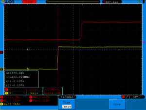
How many time MCU need to set same level on GPIO pin as on input pin?  May be 140nS (near 10 clocks on 72MHz) will enought?
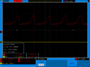
stm32_delay_O0

Nope. 480ns. It near 34 cycles. The period of 480ns has frequency of 2MHz, may be i forgot to change speed of gpio port?

stm32_debug_toggle_pin_50MHz

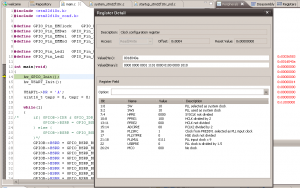
Nope. May be i forgot to switch on external quartz or forgot to configure PLL?

stm32_debug_pll

Nope. Hmm, may be optimization can help? Let’s try to switch on -O3:

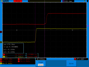
stm32_delay_O3

Much better, 170 ns. MCU need near 12 cycles, to detect signal and change state of one GPIO speed. Do not forget, MCU just pooling one pin and change state of another, it do not do valuable work.Okay, but what the maximum speed you can get, if you will just change the state of GPIO pin?
Is it possible to hit theoretical maximum of 50MHz (max clock speed of GPIO ports on STM32F103):

stm32_toggle_pin

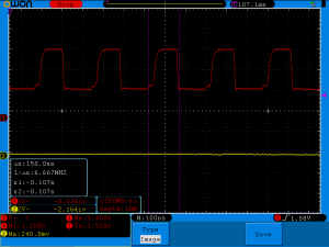
Just 6MHz. Let me switch on optimization for you:
stm32_toggle_pin_serial_0
Looks like there only 36MHz, let’s look on the code:

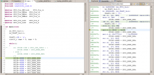
stm32_debug_toggle_pin_O3
I can’t see why they can’t reach 50MHz. If you look on disassembler view, you can see, that MCU just store different values on constant address.
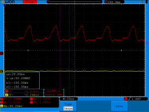
In fairness i must to say, if you set cursors on oscilloscope in different manner, you can achieve 50MHz:

stm32_toggle_pin_serial_1
It is hard to say what way of measurement is wrong, i think the second, because first time it is easy to see time of 2 periods. Without a doubt, the second way STM advertising department would have liked more.
BONUS:
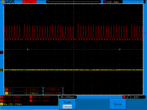
A picture where is while cycle occurs:
stm32_toggle_pin_serial_burst

Arduino keyManager

Few months ago i started to developing iron for waxing my snowboard. Last season i bought regular iron and used it, but it can set temperature only in wide range, did not have overheat protection and can melt the base of the board. In university i learned of 8bit avr mcu, but all firmwares that we wrote, we wrote on ASM. Now it is my hobby and i decided to try C/C++ programming, early at school i wrote on C, but forget to many about C language, so now, after many years without practice, i decided to try arduino.
When i wrote arduino sketches i did not found library to manage keys. I wanted event based library that can produce events when key pressed, when key long pressed and when key released, also it must have program debounce.
Early to manage keys i just wrote tonnes of code right in sketches, but when sketches grow up, they started to looks like a crap, so i develop my own library.
They far away from to be excellent ( i am not very familiar with C, not to mention C + +), but they work.
Now code of the library have mixed russian and english comments ( hope i will change it in future ).
I tried to write library fast as possible and using minimal resources, because of that (and because i do not know C++ well) there to many hard coded defines for delay values in keyManager.h (debounce time, time to long press detection and time to regenerate long press event). I feel it is possible to make library better with C++ templates, but i did not found time to learn it well.
Last words, before i show example, library designed to be used with pull up keys, ie when key pressed, digitalRead() must return LOW.
I turned arduino blink example to work with key manager. There are two keys, one switched off the led, another on switch it on.

// Include library header
 #include <keyManager.h>
 
#define led 13
#define off_pin 10
#define on_pin 11
 
// Create keyManager objects, when you create key object, they
// initialize key pin as input 
keyManager on_key( on_pin, true );
keyManager off_key( off_pin, true );
 
void setup() {
  // initialize the digital pin as an output.
  pinMode(led, OUTPUT);
}
 
// Led state
uint8_t led_state = 0;
 
void loop() {
// This is main part, process() function must run at least once in every 255 micro seconds
// process() function is heart of the library based on FSM, they process
// key state changes and generate events
  on_key.process();
  off_key.process();
 
// Light led if on key pressed
  if( on_key.isPressed() ) {
    digitalWrite(led, HIGH);
    led_state = HIGH;
  }
// Swich off if right key pressed
  if( off_key.isPressed() ) {
    digitalWrite(led, LOW);    
    led_state = LOW;
  }
 
// If any key pressed long, led will change the state
  if( on_key.isLongPressed() || off_key.isLongPressed()  ) {
    if( led_state == LOW ) {
      led_state = HIGH;
    } else {
      led_state = LOW;
    }
    digitalWrite(led, led_state);
  }
}

Second argument of:

keyManager on_key( on_pin, true );

Select how keys will be driven. When argument is ‘true’ keys will managed in ‘event mode’ it means, that isPressed() will return true only once until you did no release key and did not press it again. Same for isReleased().
isLongPressed() will return ‘true’ first time, when key will be pressed longer than defined in keyManager.h (by default 1.5 sec) and after every repeat delay if key will not released (by default 0.1 sec).
Event generated every time when key changed their state, there is function isEvent() to check that. isEvent() return true until event will not received by isPressed(), isLongPressed() or isReleased(). In another words that functions will clear event flag after picked up their event.
keyManager can work in another mode, when second argument is ‘false’, functions isPressed(), isLongPressed() and isReleased() will not clear event flag, they return true every time when key in their state. Event flag will generated as before, but can be cleared only with clearEvent() function.
Now library use 4 bytes of ram to manage single button. In future i want reduce ram that used by timers, add more examples and simplify delays configuration.

There is link to github: https://github.com/IvanBayan/arduino-keyManager